Alcatel OS6850-U24X Getting Started Guide - Page 11
Installation Options, Installing the Switch on a Tabletop or Bench, Tabletop Mounting Steps
 |
View all Alcatel OS6850-U24X manuals
Add to My Manuals
Save this manual to your list of manuals |
Page 11 highlights
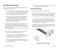
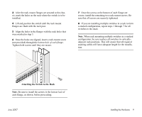
Never obstruct the air vents located at the left and right sides of the chassis. Note. Clearance is not required at the top and bottom of the chassis. For detailed chassis airflow diagrams, refer to the OmniSwitch 6850 Series Hardware Users Guide. Installation Options There are two ways in which the OmniSwitch 6850 Series switches can be installed: • Tabletop installation • Rack-mount installation For information on setting up a switch as a tabletop unit, refer to "Installing the Switch on a Tabletop or Bench." For information on rack-mounting the switch, refer to "Rack-Mounting the Switch" on page 8. Installing the Switch on a Tabletop or Bench OmniSwitch 6850 Series switches can be installed freestanding as tabletop units. Place your switch on a stable, flat, and static-free surface. Note. OmniSwitch 6850 Series switches must be placed "right side up." Never attempt to operate a switch positioned on its side. Tabletop Mounting Steps To install the switch as a tabletop unit, follow the steps below: 1 Position the chassis on the table or bench where it is to be installed. 2 Be sure that adequate clearance has been provided for chassis airflow and access to the front, back, and sides of the switch. For recommended clearances, refer to page 6. Also, be sure that you have placed the chassis within reach of all required AC power sources. If you are placing multiple switches in a stacked configuration, carefully stack the remaining switches, one on top of the other. Up to eight switches may be stacked to form a single virtual chassis. Be sure to maintain adequate clearance at the front, rear, left, and right side of all switches (see page 6). Also, be sure that you have placed all switches in the stack within reach of required AC power sources. Note. If you are installing a single (i.e., standalone) switch, continue to "Connections and Cabling" on page 11 for additional setup procedures. June 2007 Installing the Hardware 7
-
 1
1 -
2
-
3
-
4
-
5
-
 6
6 -
 7
7 -
 8
8 -
 9
9 -
 10
10 -
 11
11 -
 12
12 -
 13
13 -
 14
14 -
 15
15 -
 16
16 -
17
-
18
-
19
-
20
-
21
-
22
-
23
-
24
-
25
-
26
-
27
-
28
-
29
-
30
-
31
-
32
-
33
-
34
 |
 |