Alpine X409-WRA-JK Installation Manual EN - Page 13
X409-WRA-JK Wiring Diagram
 |
View all Alpine X409-WRA-JK manuals
Add to My Manuals
Save this manual to your list of manuals |
Page 13 highlights
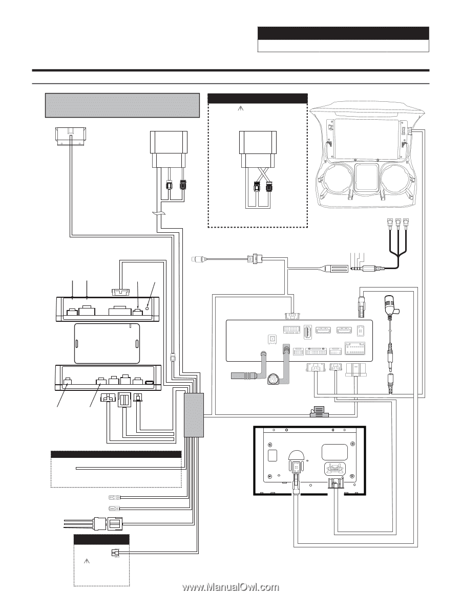
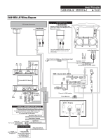
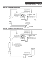
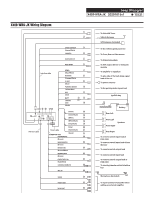
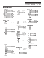
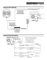
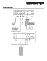
Jeep Wrangler X409-WRA-JK 20201016v1 ˜ 13/21 X409-WRA-JK Wiring Diagram To Vehicle Connectors To OBDII Connector Power/Speaker 16-pin Green Connector AMPLIFIED VEHICLES WARNING! Failure to follow this procedure will result in no audio from Navigation and Bluetooth sources. Rear Front Rear Front Front Rear Rear Front For factory amplified vehicles switch the speaker connectors, front to rear and rear to front. Audio Only No Video Audio L (White) Audio R (Red) Ground Video (Yellow) (Yellow) (Red) (White) 18-pin Black Connector Not Not Used Used Red Not Reset Used Button Direct Camera Adapter Direct Camera Input Aux Input Aux Input Cable (Sold Separate 3rd Party Cable) Microphone 10-Pin Chime 18-Pin iDatalink MAESTRO Module 3-Pin 4-Pin 10-Pin 3-Pin 4-Pin X409 - Source Unit CAN I/F GPS SXM/DAB USB HDMI IN DISP. OUT HDMI OUT ANTENNA PRE OUT EXT. KEY W.REMOTE POWER 10-pin Green Connector (Vehicle signals) 3-pin Black Connector (Power) 4-pin Black Connector (Data) Main Harness Not Used Blue Not Used *If using KAC-001 see page 19 MANUAL TRANSMISSION VEHICLES White/Gray Manual Transmission Reverse Input For manual transmission vehicles ONLY. Connect the White/Gray wire to the White/Gray wire located on the passenger side kick panel. Blue/White Amp Turn-on Blue Power Antenna Yellow -12V+ Red - Acc 12V+ Black - Ground AUX Power 3-pin Black Connector Rear View Camera Rear View Camera 6-pin Black Connector If using HCE-TCAM1-WRA WARNING! see page 18 The use of this connection is intended for Alpine HCE-TCAM1-WRA rear view camera ONLY. Connect to SXM adapter Power Harness X409 - Display
-
 1
1 -
2
-
3
-
4
-
5
-
6
-
7
-
 8
8 -
 9
9 -
 10
10 -
 11
11 -
 12
12 -
 13
13 -
 14
14 -
 15
15 -
 16
16 -
 17
17 -
 18
18 -
19
-
20
-
21
 |
 |