Apple M8760LL Service Guide - Page 25
Preliminary Steps, Procedure, Place the computer face down on a soft cloth. - cases
 |
UPC - 718908426234
View all Apple M8760LL manuals
Add to My Manuals
Save this manual to your list of manuals |
Page 25 highlights
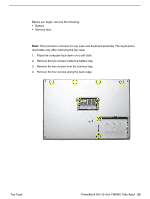
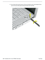
Preliminary Steps Before you begin, remove the following: • Battery • Memory door Procedure Note: This procedure removes the top case and keyboard assembly. The keyboard is removable only after removing the top case. 1. Place the computer face down on a soft cloth. 2. Remove the two screws inside the battery bay. 3. Remove the two screws from the memory bay. 4. Remove the four screws along the back edge. Top Case PowerBook G4 (15-inch FW800) Take Apart - 23
-
 1
1 -
2
-
3
-
4
-
5
-
6
-
7
-
8
-
9
-
10
-
11
-
12
-
13
-
14
-
15
-
16
-
17
-
18
-
19
-
 20
20 -
 21
21 -
 22
22 -
 23
23 -
 24
24 -
 25
25 -
 26
26 -
 27
27 -
 28
28 -
 29
29 -
 30
30 -
31
-
32
-
33
-
34
-
35
-
36
-
37
-
38
-
39
-
40
-
41
-
42
-
43
-
44
-
45
-
46
-
47
-
48
-
49
-
50
-
51
-
52
-
53
-
54
-
55
-
56
-
57
-
58
-
59
-
60
-
61
-
62
-
63
-
64
-
65
-
66
-
67
-
68
-
69
-
70
-
71
-
72
-
73
-
74
-
75
-
76
-
77
-
78
-
79
-
80
-
81
-
82
-
83
-
84
-
85
-
86
-
87
-
88
-
89
-
90
-
91
-
92
-
93
-
94
-
95
-
96
-
97
-
98
-
99
-
100
-
101
-
102
-
103
-
104
-
105
-
106
-
107
-
108
-
109
-
110
-
111
-
112
-
113
-
114
-
115
-
116
-
117
-
118
-
119
-
120
-
121
-
122
-
123
-
124
-
125
-
126
-
127
-
128
-
129
-
130
-
131
-
132
-
133
-
134
-
135
-
136
-
137
-
138
-
139
-
140
-
141
-
142
-
143
-
144
-
145
-
146
-
147
-
148
-
149
-
150
-
151
-
152
 |
 |

PowerBook G4 (15-inch FW800) Take Apart -
23
Top Case
Preliminary Steps
Before you begin, remove the following:
•
Battery
•
Memory door
Procedure
Note:
This procedure removes the top case and keyboard assembly. The keyboard is
removable only after removing the top case.
1.
Place the computer face down on a soft cloth.
2.
Remove the two screws inside the battery bay.
3.
Remove the two screws from the memory bay.
4.
Remove the four screws along the back edge.