Apple M8760LL Service Guide - Page 95
the flex cable, then tighten in the following order., in and that the eject button works smoothly.
 |
UPC - 718908426234
View all Apple M8760LL manuals
Add to My Manuals
Save this manual to your list of manuals |
Page 95 highlights
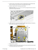
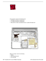
4. Verify the holes in the Sound/DC-in board, are aligned with the screw bosses under them on the bottom case so that the PC card cage screws will install. 5. Install the replacement PC card cage and eject button. Replacement Note: Ensure that the pin on the PC card cage eject button is secured by the hole in the cage mechanism. 6. Lightly install all four screws before tightening (note: longer screws go in the back by the flex cable), then tighten in the following order. 7. Reassemble the computer. 8. Testing the computer should include inserting a PC card to check that it can be locked in and that the eject button works smoothly. PC Card Cage PowerBook G4 (15-inch FW800) Take Apart - 93
-
 1
1 -
2
-
3
-
4
-
5
-
6
-
7
-
8
-
9
-
10
-
11
-
12
-
13
-
14
-
15
-
16
-
17
-
18
-
19
-
20
-
21
-
22
-
23
-
24
-
25
-
26
-
27
-
28
-
29
-
30
-
31
-
32
-
33
-
34
-
35
-
36
-
37
-
38
-
39
-
40
-
41
-
42
-
43
-
44
-
45
-
46
-
47
-
48
-
49
-
50
-
51
-
52
-
53
-
54
-
55
-
56
-
57
-
58
-
59
-
60
-
61
-
62
-
63
-
64
-
65
-
66
-
67
-
68
-
69
-
70
-
71
-
72
-
73
-
74
-
75
-
76
-
77
-
78
-
79
-
80
-
81
-
82
-
83
-
84
-
85
-
86
-
87
-
88
-
89
-
 90
90 -
 91
91 -
 92
92 -
 93
93 -
 94
94 -
 95
95 -
 96
96 -
 97
97 -
 98
98 -
 99
99 -
 100
100 -
101
-
102
-
103
-
104
-
105
-
106
-
107
-
108
-
109
-
110
-
111
-
112
-
113
-
114
-
115
-
116
-
117
-
118
-
119
-
120
-
121
-
122
-
123
-
124
-
125
-
126
-
127
-
128
-
129
-
130
-
131
-
132
-
133
-
134
-
135
-
136
-
137
-
138
-
139
-
140
-
141
-
142
-
143
-
144
-
145
-
146
-
147
-
148
-
149
-
150
-
151
-
152
 |
 |

PowerBook G4 (15-inch FW800) Take Apart -
93
PC Card Cage
4.
Verify the holes in the Sound/DC-in board, are aligned with the screw bosses under
them on the bottom case so that the PC card cage screws will install.
5.
Install the replacement PC card cage and eject button.
Replacement Note:
Ensure that the pin on the PC card cage eject button is secured
by the hole in the cage mechanism.
6.
Lightly install all four screws before tightening (
note:
longer screws go in the back by
the flex cable), then tighten in the following order.
7.
Reassemble the computer.
8.
Testing the computer should include inserting a PC card to check that it can be locked
in and that the eject button works smoothly.