Asus AP1600R User Guide - Page 49
Layout contents
 |
View all Asus AP1600R manuals
Add to My Manuals
Save this manual to your list of manuals |
Page 49 highlights
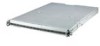
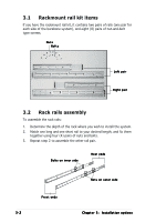
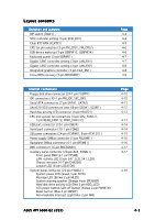
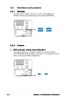
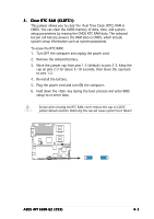
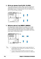
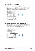
Layout contents Switches and jumpers DIP switch (DSW1) SCSI controller setting (3-pin SCSI_EN1) Clear RTC RAM (CLRTC1) CPU fan pin selection (3-pin FM_CPU1, FM_CPU2) USB device wake-up (3-pin USBPW12, USBPW34) Keyboard power (3-pin KBPWR1) Gigabit LAN1 controller setting (3-pin LAN_EN1) Gigabit LAN2 controller setting (3-pin LAN_EN2) Integrated graphics controller (3-pin VGA_EN1) Force BIOS recovery (3-pin RECOVERY) Page 4-4 4-4 4-5 4-6 4-6 4-7 4-7 4-8 4-8 4-9 Internal connectors Floppy disk drive connector (34-1 pin FLOPPY) IDE connectors (40-1 pin PRI_IDE, SEC_IDE) Serial ATA connectors (7-pin SATA1, SATA2) Ultra320 SCSI connectors (two 68-pin SCSIA1, SCSIB1) Hard disk activity LED connector (4-pin HDLED1) CPU and system fan connectors (4-pin CPU_FAN1/2, 3-pin REAR_FAN1/2, FRNT_FAN1/2) USB port connector (10-1 pin USB34) Serial port connector (10-1 pin COM2) SSI power connectors (24-pin ATXPWR1, 8-pin ATX12V1) Power supply SMBus connector (5-pin PSUSMB1) Backplane SMBus connector (6-1 pin BPSMB1) BMC connector (16-pin BMCCONN1) Auxiliary panel connector (20-pin AUX_PANEL1) Front panel SMB (6-1 pin FPSMB) LAN activity LED (2-pin 547_LED, 541_LED) Chassis intrusion (4-1 pin CHASSIS) Locator LED (6-pin LOCATOR) System panel connector (20-pin PANEL1) System power LED (Green 3-pin PLED) Message LED (Brown 2-pin MLED) System warning speaker (Orange 4-pin SPEAKER) Hard disk drive activity LED (Red 2-pin HDD_LED) ATX power button/soft-off button (Yellow 2-pin PWRBTN) Reset button (Blue 2-pin RESET) Non-maskable interrupt (Light blue 2-pin NMI) Page 4-10 4-10 4-11 4-12 4-13 4-13 4-14 4-14 4-15 4-16 4-16 4-17 4-17 4-18 ASUS AP1600R-E2 (CS3) 4-3
-
 1
1 -
2
-
3
-
4
-
5
-
6
-
7
-
8
-
9
-
10
-
11
-
12
-
13
-
14
-
15
-
16
-
17
-
18
-
19
-
20
-
21
-
22
-
23
-
24
-
25
-
26
-
27
-
28
-
29
-
30
-
31
-
32
-
33
-
34
-
35
-
36
-
37
-
38
-
39
-
40
-
41
-
42
-
43
-
 44
44 -
 45
45 -
 46
46 -
 47
47 -
 48
48 -
 49
49 -
 50
50 -
 51
51 -
 52
52 -
 53
53 -
 54
54 -
55
-
56
-
57
-
58
-
59
-
60
-
61
-
62
-
63
-
64
-
65
-
66
-
67
-
68
-
69
-
70
-
71
-
72
-
73
-
74
-
75
-
76
-
77
-
78
-
79
-
80
-
81
-
82
-
83
-
84
-
85
-
86
-
87
-
88
-
89
-
90
-
91
-
92
-
93
-
94
-
95
-
96
-
97
-
98
-
99
-
100
-
101
-
102
-
103
-
104
 |
 |