Asus AP1600R User Guide - Page 59
Pin Rear_fan1/2, Frnt_fan1/2
 |
View all Asus AP1600R manuals
Add to My Manuals
Save this manual to your list of manuals |
Page 59 highlights
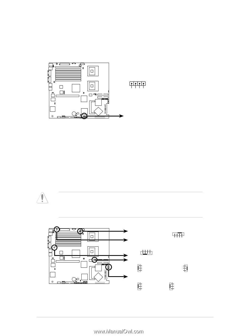
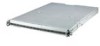
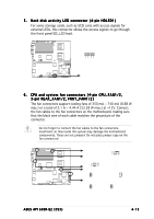
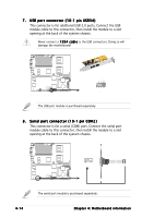
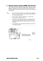
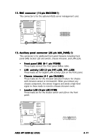
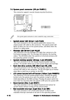
5 . Hard disk activity LED connector (4-pin HDLED1) For some storage cards, such as SCSI card, with access signals for external LEDs, this connector allows the access signals to go through the front panel IDE_LED lead. HDLED1 1 ® NCL-DS1R1 SCSI_ACTLED+ SCSI_ACTLEDSCSI_ACTLEDSCSI_ACTLED+ NCL-DS1R1 SCSI/SATA card activity LED connector 6 . CPU and system fan connectors (4-pin CPU_FAN1/2, 3-pin REAR_FAN1/2, FRNT_FAN1/2) The fan connectors support cooling fans of 350 mA ~ 740 mA (8.88 W max.) or a total of 2.1 A ~ 4.44 A (53.28 W max.) at +12V. Connect the fan cables to the fan connectors on the motherboard, making sure that the black wire of each cable matches the ground pin of the connector. Do not forget to connect the fan cables to the fan connectors. Insufficient air flow inside the system may damage the motherboard components. These are not jumpers! Do not place jumper caps on the fan connectors! CPU_FAN1 REAR_FAN2 CPU_FAN1 CPU_FAN2 ® NCL-DS1R1 GND FAN Power FAN Speed PWM Control PWM Control FAN Speed FAN Power GND REAR_FAN1 CPU_FAN2 FRNT_FAN1 FRNT_FAN2 NCL-DS1R1 Fan connectors REAR_FAN1 GND +12V Rotation FRNT_FAN1 GND +12V Rotation REAR_FAN2 Rotation +12V GND FRNT_FAN2 GND +12V Rotation ASUS AP1600R-E2 (CS3) 4-13
-
 1
1 -
2
-
3
-
4
-
5
-
6
-
7
-
8
-
9
-
10
-
11
-
12
-
13
-
14
-
15
-
16
-
17
-
18
-
19
-
20
-
21
-
22
-
23
-
24
-
25
-
26
-
27
-
28
-
29
-
30
-
31
-
32
-
33
-
34
-
35
-
36
-
37
-
38
-
39
-
40
-
41
-
42
-
43
-
44
-
45
-
46
-
47
-
48
-
49
-
50
-
51
-
52
-
53
-
 54
54 -
 55
55 -
 56
56 -
 57
57 -
 58
58 -
 59
59 -
 60
60 -
 61
61 -
 62
62 -
 63
63 -
 64
64 -
65
-
66
-
67
-
68
-
69
-
70
-
71
-
72
-
73
-
74
-
75
-
76
-
77
-
78
-
79
-
80
-
81
-
82
-
83
-
84
-
85
-
86
-
87
-
88
-
89
-
90
-
91
-
92
-
93
-
94
-
95
-
96
-
97
-
98
-
99
-
100
-
101
-
102
-
103
-
104
 |
 |