Asus AP6000 Hardware Reference - Page 20
Hot-Swap Tray Connector Board
 |
View all Asus AP6000 manuals
Add to My Manuals
Save this manual to your list of manuals |
Page 20 highlights
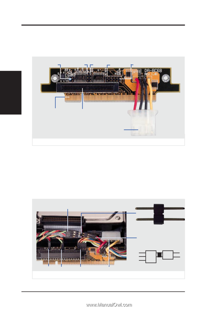
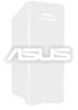
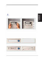
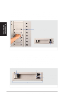
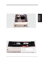
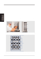
II. System Components Hot-Swap Tray Connector Board The connector board is mounted on the hot-swap tray to interface with the SCSI backplane in the chassis. The connector board provides combines all the signal and power into one docking connector for a clean hot-swap unit. SLED KEY (not used) ALED_IN PLED (not used) SCSI_ID II. Components Hot-Swap Connector Hot-Swap Tray Wide SCSI Docking Connector Connector Hard Disk Drive Power Connector Hot-swap tray connector board parts Hot-Swap Tray Rear Connections KEY: These 2 pins connect to the keylock on the tray's front panel to turn on and off the drive's power. PLED: These 2 pins connect to the power LED on the front of the tray to show when the connector board receives power. SCSI_ID: These 8 pins connect to the hard disk drive's SCSI address pins to set the SCSI ID number of the hard disk drive. SLED & ALED: These two wires are connected as illustrated below. from tray's front panel 3 pin activity LED (SLED wire) Connector Bridge for LED KEY PLED SCSI_ID Power Hot-swap tray rear connections (Seagate HD) from hard disk drive's 2 pin activity LED (ALED wire) Bridge Green Black Red SLED (wire) Red Black ALED (wire) 20 AP6000 Hardware Reference Guide
-
 1
1 -
2
-
3
-
4
-
5
-
6
-
7
-
8
-
9
-
10
-
11
-
12
-
13
-
14
-
 15
15 -
 16
16 -
 17
17 -
 18
18 -
 19
19 -
 20
20 -
 21
21 -
 22
22 -
 23
23 -
 24
24 -
 25
25 -
26
-
27
-
28
-
29
-
30
-
31
-
32
 |
 |