Asus AP6000 Hardware Reference - Page 22
SCSI Board Placement
 |
View all Asus AP6000 manuals
Add to My Manuals
Save this manual to your list of manuals |
Page 22 highlights
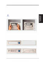
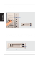
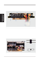
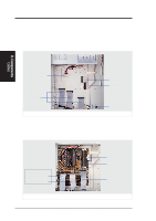
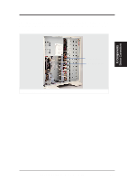
II. Components SCSI Backplane II. System Components SCSI Backplane The SCSI backplane of this server is comprised of two SCSI boards with a Wide-SCSI connector, power input, and SCSI ID dip switches on each SCSI board. This configuration allows Wide-SCSI hard disk drives to be docked into the server using a common connector. The female end is located on the SCSI board, while the male end is located on the hot-swap tray. SCSI Board Placement There are three screws on each side of the SCSI board. Both sides of the cabinet side panels must be removed to access these screws. Please note that notches on the top and bottom of the SCSI board must be placed as shown in order to properly seat the SCSI boards into the chassis. The SCSI board will only fit in one orientation but may be interchanged between the top and bottom half but be aware of the SCSI ID setting of each board. Top Half Bottom Half SCSI board placement Notch Out (top) Four SCSI Board Docking Connectors SCSI board front side Notch In (bottom) 22 AP6000 Hardware Reference Guide
-
 1
1 -
2
-
3
-
4
-
5
-
6
-
7
-
8
-
9
-
10
-
11
-
12
-
13
-
14
-
15
-
16
-
 17
17 -
 18
18 -
 19
19 -
 20
20 -
 21
21 -
 22
22 -
 23
23 -
 24
24 -
 25
25 -
 26
26 -
 27
27 -
28
-
29
-
30
-
31
-
32
 |
 |