Asus AW1500-S5 AW1500-I5 English Manual - Page 46
SCSI Backplane frontside and backside
 |
View all Asus AW1500-S5 manuals
Add to My Manuals
Save this manual to your list of manuals |
Page 46 highlights
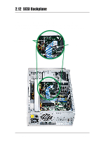
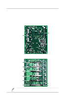
2.12.2 SCSI Backplane frontside and backside The SCSI backplane assembly of this server is comprised of one SCSI board (BP6LS-AS35) with 68-pin SCSI connector, two 12V power inputs, two fan connectors (FAN1, FAN2) and three jumper connectors (J1, J2, J3). This configuration allows SCA SCSI hard disk drives to be docked into the server. A. SCSI Backplane Frontside Power connectors SCSI 68-pin connector 2-26 SCSI ID = 0 (Disk Drive 1) SCSI ID = 1 (Disk Drive 2) SCSI ID = 2 (Disk Drive 3) SCSI ID = 3 (Disk Drive 4) SCSI ID = 4 (Disk Drive 5) SCSI ID = 5 (Disk Drive 6) B. SCSI Backplane Backside HD activity LED HD status LED Refer to "1.5 LED Table" on page 1-8, for detailed SCSI Backplane LED display descriptions. ASUS AW1500-S5
-
 1
1 -
2
-
3
-
4
-
5
-
6
-
7
-
8
-
9
-
10
-
11
-
12
-
13
-
14
-
15
-
16
-
17
-
18
-
19
-
20
-
21
-
22
-
23
-
24
-
25
-
26
-
27
-
28
-
29
-
30
-
31
-
32
-
33
-
34
-
35
-
36
-
37
-
38
-
39
-
40
-
 41
41 -
 42
42 -
 43
43 -
 44
44 -
 45
45 -
 46
46 -
 47
47 -
 48
48 -
 49
49 -
 50
50 -
 51
51 -
52
-
53
-
54
-
55
-
56
 |
 |

2-26
ASUS AW1500-S5
2.12.2
SCSI Backplane frontside and backside
The SCSI backplane assembly of this server is comprised of one SCSI
board (BP6LS-AS35) with 68-pin SCSI connector, two 12V power inputs,
two fan connectors (FAN1, FAN2) and three jumper connectors (J1, J2,
J3). This configuration allows SCA SCSI hard disk drives to be docked into
the server.
Power connectors
SCSI 68-pin
connector
A. SCSI Backplane Frontside
Refer to “1.5 LED Table” on page 1-8, for detailed SCSI Backplane
LED display descriptions.
B. SCSI Backplane Backside
SCSI ID = 0
(Disk Drive 1)
HD status LED
HD activity LED
SCSI ID = 1
(Disk Drive 2)
SCSI ID = 2
(Disk Drive 3)
SCSI ID = 3
(Disk Drive 4)
SCSI ID = 4
(Disk Drive 5)
SCSI ID = 5
(Disk Drive 6)