Asus BP5265 User Manual - Page 15
Rear panel
 |
View all Asus BP5265 manuals
Add to My Manuals
Save this manual to your list of manuals |
Page 15 highlights
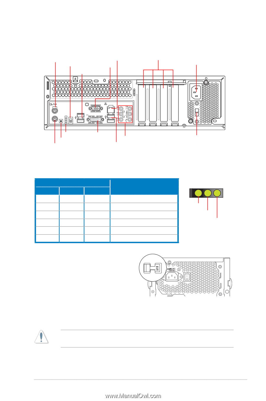
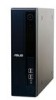
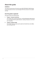
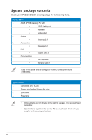
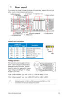
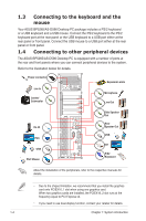
1.2 Rear panel The system rear panel includes the power connector and several I/O ports that allow you to conveniently connect devices. 1 x PS/2 Mouse port 1 x RJ-45 port 1 x ME Switch 1 x VGA port 2 x USB 2.0 ports 4 x Expansion slots 1 x Power connector 15 Debug LED 1x DVI port Clear CMOS button 8-channel audio ports 1 x PS/2 Keyboard port 2 x USB 2.0 ports 1 x Voltage selector Debug LED indications Debug LED Left Middle Right ON OFF OFF OFF ON OFF ON ON OFF OFF OFF ON ON OFF ON OFF ON ON Description Detecting system memory Initializing VGA Initializing CPU Detecting Hard Disk Drive BIOS error message Initializing ROM Left Middle Right Voltage selector The system's power supply unit has a 115V / 230V voltage selector located below the power connector. Use this switch to select the appropriate system input voltage according to the voltage supply in your area. If the voltage supply in your area is 100-127V, set the switch to 115V. If the voltage supply in your area is 200-240V, set the switch to 230V. Setting the switch to 115V in a 230V environment or 230V in a 115V environment will seriously damage the system! ASUS BP5265/AS-D596 1-3
-
 1
1 -
2
-
3
-
4
-
5
-
6
-
7
-
8
-
9
-
 10
10 -
 11
11 -
 12
12 -
 13
13 -
 14
14 -
 15
15 -
 16
16 -
 17
17 -
 18
18 -
 19
19 -
 20
20 -
21
-
22
-
23
-
24
-
25
-
26
-
27
-
28
-
29
-
30
-
31
-
32
-
33
-
34
-
35
-
36
-
37
-
38
-
39
-
40
-
41
-
42
-
43
-
44
-
45
-
46
-
47
-
48
-
49
-
50
-
51
-
52
-
53
-
54
-
55
-
56
-
57
-
58
-
59
-
60
-
61
-
62
-
63
-
64
-
65
-
66
-
67
-
68
-
69
-
70
-
71
-
72
-
73
-
74
-
75
-
76
 |
 |