Asus COMMANDO Commando User's Manual for English Edtion - Page 52
ICH8R Serial ATA connectors, pin SATA1, SATA2, SATA3, SATA4, SATA5, SATA6
 |
View all Asus COMMANDO manuals
Add to My Manuals
Save this manual to your list of manuals |
Page 52 highlights
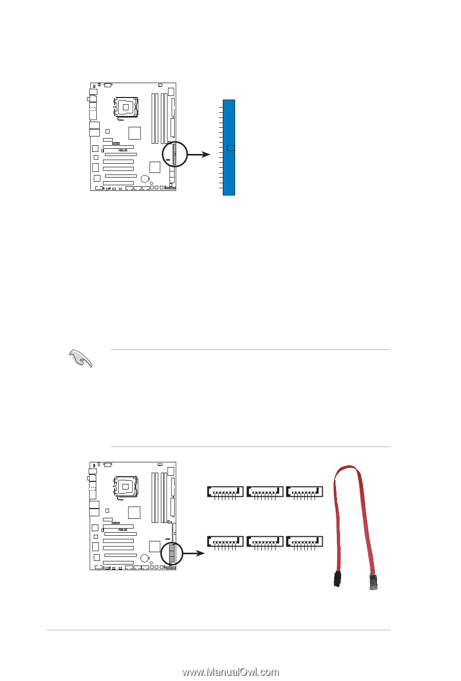
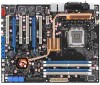
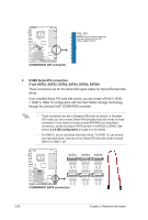
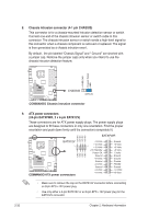
® COMMANDO PRI_IDE NOTE: Orient the red markings (usually zigzag) on the IDE ribbon cable to PIN 1. COMMANDO IDE connector 3. ICH8R Serial ATA connectors (7-pin SATA1, SATA2, SATA3, SATA4, SATA5, SATA6) These connectors are for the Serial ATA signal cables for Serial ATA hard disk drives. If you installed Serial ATA hard disk drives, you can create a RAID 0, RAID 1, RAID 5, RAID 10 configuration with the Intel® Matrix Storage Technology through the onboard Intel® ICH8R RAID controller. • These connectors are set to Standard IDE mode by default. In Standard IDE mode, you can connect Serial ATA boot/data hard disk drives to these connectors. If you intend to create a Serial ATA RAID set using these connectors, set the [Configure SATA as] item in the BIOS to [RAID]. See section 4.3.6 IDE Configuration on page 4-14 for details. • For RAID 5, use at least three hard disk drives. For RAID 10, use at least four hard disk drives. Use two to four Serial ATA hard disk drives for each RAID 0 or RAID 1 set. SATA1 SATA3 SATA5 GND RSATA_RXN5 RSATA_RXP5 GND RSATA_TXN5 RSATA_TXP5 GND GND RSATA_RXN3 RSATA_RXP3 GND RSATA_TXN3 RSATA_TXP3 GND GND RSATA_RXN1 RSATA_RXP1 GND RSATA_TXN1 RSATA_TXP1 GND ® COMMANDO SATA2 SATA4 SATA6 GND RSATA_RXN6 RSATA_RXP6 GND RSATA_TXN6 RSATA_TXP6 GND GND RSATA_RXN4 RSATA_RXP4 GND RSATA_TXN4 RSATA_TXP4 GND GND RSATA_RXN2 RSATA_RXP2 GND RSATA_TXN2 RSATA_TXP2 GND COMMANDO SATA connectors 2-28 Chapter 2: Hardware information
-
 1
1 -
2
-
3
-
4
-
5
-
6
-
7
-
8
-
9
-
10
-
11
-
12
-
13
-
14
-
15
-
16
-
17
-
18
-
19
-
20
-
21
-
22
-
23
-
24
-
25
-
26
-
27
-
28
-
29
-
30
-
31
-
32
-
33
-
34
-
35
-
36
-
37
-
38
-
39
-
40
-
41
-
42
-
43
-
44
-
45
-
46
-
 47
47 -
 48
48 -
 49
49 -
 50
50 -
 51
51 -
 52
52 -
 53
53 -
 54
54 -
 55
55 -
 56
56 -
 57
57 -
58
-
59
-
60
-
61
-
62
-
63
-
64
-
65
-
66
-
67
-
68
-
69
-
70
-
71
-
72
-
73
-
74
-
75
-
76
-
77
-
78
-
79
-
80
-
81
-
82
-
83
-
84
-
85
-
86
-
87
-
88
-
89
-
90
-
91
-
92
-
93
-
94
-
95
-
96
-
97
-
98
-
99
-
100
-
101
-
102
-
103
-
104
-
105
-
106
-
107
-
108
-
109
-
110
-
111
-
112
-
113
-
114
-
115
-
116
-
117
-
118
-
119
-
120
-
121
-
122
-
123
-
124
-
125
-
126
-
127
-
128
-
129
-
130
-
131
-
132
-
133
-
134
-
135
-
136
-
137
-
138
-
139
-
140
-
141
-
142
-
143
-
144
-
145
-
146
-
147
-
148
-
149
-
150
-
151
-
152
-
153
-
154
 |
 |