Asus COMMANDO Commando User's Manual for English Edtion - Page 54
IEEE 1394a port connector 10-1 pin IE1394_2, Thermal sensor cable connectors 2-pin OPT_TEMP1/2/3
 |
View all Asus COMMANDO manuals
Add to My Manuals
Save this manual to your list of manuals |
Page 54 highlights
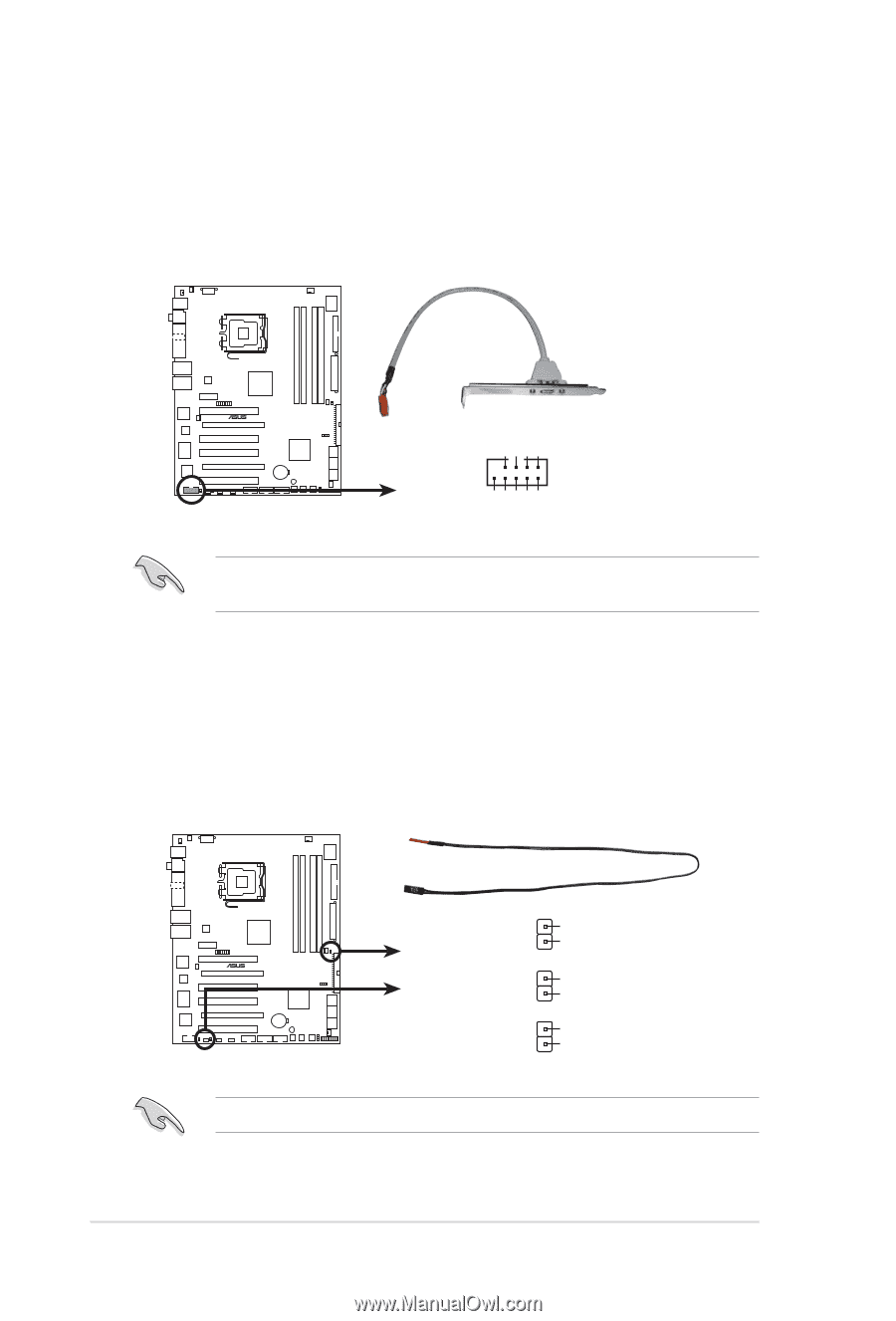
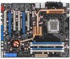
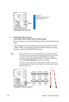
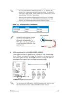
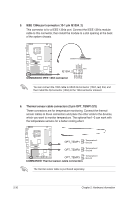
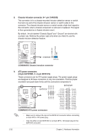
5. IEEE 1394a port connector (10-1 pin IE1394_2) This connector is for a IEEE 1394a port. Connect the IEEE 1394a module cable to this connector, then install the module to a slot opening at the back of the system chassis. ® COMMANDO PIN1 IE1394_2 +12V TPB2+ GND TPA2+ GND +12V TPB2GND TPA2- COMMANDO IEEE 1394 connector You can connect the 1394 cable to ASUS Q-Connector (1394, red) first, and then install the Q-Connector (1394) to the 1394 connector onboard. 6. Thermal sensor cable connectors (2-pin OPT_TEMP1/2/3) These connectors are for temperature monitoring. Connect the thermal sensor cables to these connectors and place the other ends to the devices, which you want to monitor temperature. The optional fan1~3 can work with the temperature sensors for a better cooling effect. ® COMMANDO OPT_TEMP1 OPT_TEMP2 Temperature1 Ground Temperature2 Ground OPT_TEMP3 Temperature3 Ground COMMANDO Thermal sersor cable connectors The thermal sensor cable is purchased separately. 2-30 Chapter 2: Hardware information
-
 1
1 -
2
-
3
-
4
-
5
-
6
-
7
-
8
-
9
-
10
-
11
-
12
-
13
-
14
-
15
-
16
-
17
-
18
-
19
-
20
-
21
-
22
-
23
-
24
-
25
-
26
-
27
-
28
-
29
-
30
-
31
-
32
-
33
-
34
-
35
-
36
-
37
-
38
-
39
-
40
-
41
-
42
-
43
-
44
-
45
-
46
-
47
-
48
-
 49
49 -
 50
50 -
 51
51 -
 52
52 -
 53
53 -
 54
54 -
 55
55 -
 56
56 -
 57
57 -
 58
58 -
 59
59 -
60
-
61
-
62
-
63
-
64
-
65
-
66
-
67
-
68
-
69
-
70
-
71
-
72
-
73
-
74
-
75
-
76
-
77
-
78
-
79
-
80
-
81
-
82
-
83
-
84
-
85
-
86
-
87
-
88
-
89
-
90
-
91
-
92
-
93
-
94
-
95
-
96
-
97
-
98
-
99
-
100
-
101
-
102
-
103
-
104
-
105
-
106
-
107
-
108
-
109
-
110
-
111
-
112
-
113
-
114
-
115
-
116
-
117
-
118
-
119
-
120
-
121
-
122
-
123
-
124
-
125
-
126
-
127
-
128
-
129
-
130
-
131
-
132
-
133
-
134
-
135
-
136
-
137
-
138
-
139
-
140
-
141
-
142
-
143
-
144
-
145
-
146
-
147
-
148
-
149
-
150
-
151
-
152
-
153
-
154
 |
 |