Asus COMMANDO Commando User's Manual for English Edtion - Page 55
CPU, chassis, power, and optional fan connectors, pin CPU_FAN, 3-pin CHA_FAN1, 3-pin CHA_FAN2, 3-pin - cpu support
 |
View all Asus COMMANDO manuals
Add to My Manuals
Save this manual to your list of manuals |
Page 55 highlights
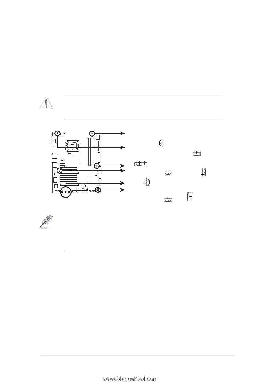
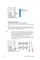
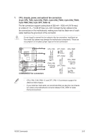
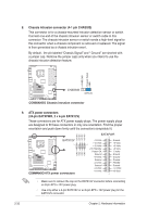
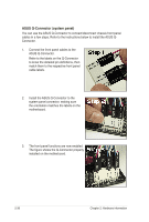
7. CPU, chassis, power, and optional fan connectors (4-pin CPU_FAN, 3-pin CHA_FAN1, 3-pin CHA_FAN2, 3-pin CHA_FAN3, 3-pin PWR_FAN, 3‑pin OPT_FAN1~3) The fan connectors support cooling fans of 350 mA ~ 2000 mA (24 W max.) or a total of 1 A ~ 7 A (84 W max.) at +12V. Connect the fan cables to the fan connectors on the motherboard, making sure that the black wire of each cable matches the ground pin of the connector. Do not forget to connect the fan cables to the fan connectors. Insufficient air flow inside the system may damage the motherboard components. These are not jumpers! Do not place jumper caps on the fan connectors! CPU_FAN PWR_FAN ® COMMANDO OPT_FAN1 CHA_FAN2 OPT_FAN3 OPT_FAN2 CHA_FAN1 CHA_FAN3 COMMANDO Fan connectors GND CPU FAN PWR CPU FAN IN CPU FAN PWM CPU_FAN OPT_FAN1 GND +12V Rotation OPT_FAN2 GND +12V Rotation CHA_FAN1 GND +12V Rotation PWR_FAN Rotation +12V GND GND +12V Rotation OPT_FAN3 CHA_FAN2 Rotation +12V GND CHA_FAN3 GND +12V Rotation • CPU_FAN, CHA_FAN1~3, and OPT_FAN 1~3 connectors support the ASUS Q-FAN 2 feature. • If you install two VGA cards, we recommend that you plug the rear chassis fan cable to the motherboard connector labeled CHA_FAN2 for better themal environment. ASUS Commando 2-31
-
 1
1 -
2
-
3
-
4
-
5
-
6
-
7
-
8
-
9
-
10
-
11
-
12
-
13
-
14
-
15
-
16
-
17
-
18
-
19
-
20
-
21
-
22
-
23
-
24
-
25
-
26
-
27
-
28
-
29
-
30
-
31
-
32
-
33
-
34
-
35
-
36
-
37
-
38
-
39
-
40
-
41
-
42
-
43
-
44
-
45
-
46
-
47
-
48
-
49
-
 50
50 -
 51
51 -
 52
52 -
 53
53 -
 54
54 -
 55
55 -
 56
56 -
 57
57 -
 58
58 -
 59
59 -
 60
60 -
61
-
62
-
63
-
64
-
65
-
66
-
67
-
68
-
69
-
70
-
71
-
72
-
73
-
74
-
75
-
76
-
77
-
78
-
79
-
80
-
81
-
82
-
83
-
84
-
85
-
86
-
87
-
88
-
89
-
90
-
91
-
92
-
93
-
94
-
95
-
96
-
97
-
98
-
99
-
100
-
101
-
102
-
103
-
104
-
105
-
106
-
107
-
108
-
109
-
110
-
111
-
112
-
113
-
114
-
115
-
116
-
117
-
118
-
119
-
120
-
121
-
122
-
123
-
124
-
125
-
126
-
127
-
128
-
129
-
130
-
131
-
132
-
133
-
134
-
135
-
136
-
137
-
138
-
139
-
140
-
141
-
142
-
143
-
144
-
145
-
146
-
147
-
148
-
149
-
150
-
151
-
152
-
153
-
154
 |
 |