Asus CUWE-RM CUWE-RM User Manual - Page 12

Features and Component Locations - cuw am manual

Page 12 highlights

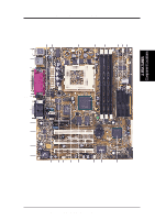
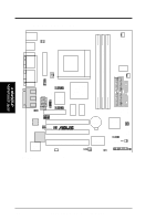
2. FEATURES Component Locations 2. FEATURES 2.2 Features and Component Locations See opposite page for locations. Location Processor Support Socket 370 for Coppermine/Mendocino Processors 3 Feature Setting DIP Switches 7 66MHz to 166MHz bus support (24 external clock settings) Chipsets Intel 810E Integrated Graphics Chipset 4 Graphics Memory Controller Hub (GMCH) Intel I/O Controller Hub (ICH 9 4Mb Firmware Hub (FWH 17 Low Pin Count Multi-I/O Chipset 13 Main Memory Maximum 512MB support 3 DIMM Sockets 5 PC100 SDRAM support Expansion Slots 3 PCI Slots 16 1 Audio Modem Riser (AMR) Slot 20 System I/O 2 IDE Connectors (UltraDMA33/66 Support 6 1 Floppy Disk Driver Connector 8 1 Serial COM1 Connector 24 1 Parallel Port Connector 23 2 USB Connectors 25 1 PS/2 Mouse Connector Top) 26 1 PS/2 Keyboard Connector Bottom) 26 1 Serial Header 1 3D Graphics Graphics Memory Controller Hub (GMCH) 1 VGA Monitor Output Connector 22 TV/Digital LCD Headers 15 4MB onboard high-speed SDRAM 12 Audio Yamaha PCI Audio (optional 18 AC'97 V2.1 Audio Codec (optional 19 1 Joystick/MIDI Connector (on audio model only) .... (Top ) 21 1 Line Out Connector (on audio model only) ........ (Bottom) 21 1 Line In Connector (on audio model only Bottom) 21 1 Microphone Connector (on audio model only) ... (Bottom) 21 Network Features Wake-On-LAN Connector 14 Wake-On-Ring Connector 11 Hardware Monitoring System Voltage Monitoring (integrated in ASUS ASIC) ....... 10 3 Fan Power and Speed Monitoring Connectors Power ATX Power Supply Connector 2 Form Factor microATX, 8.25" x 9.625" (210mm x 245mm) 12 ASUS CUWE-RM User's Manual

  • 1
  • 2
  • 3
  • 4
  • 5
  • 6
  • 7
  • 8
  • 9
  • 10
  • 11
  • 12
  • 13
  • 14
  • 15
  • 16
  • 17
  • 18
  • 19
  • 20
  • 21
  • 22
  • 23
  • 24
  • 25
  • 26
  • 27
  • 28
  • 29
  • 30
  • 31
  • 32
  • 33
  • 34
  • 35
  • 36
  • 37
  • 38
  • 39
  • 40
  • 41
  • 42
  • 43
  • 44
  • 45
  • 46
  • 47
  • 48
  • 49
  • 50
  • 51
  • 52
  • 53
  • 54
  • 55
  • 56
  • 57
  • 58
  • 59
  • 60
  • 61
  • 62
  • 63
  • 64
  • 65
  • 66
  • 67
  • 68
  • 69
  • 70
  • 71
  • 72
  • 73
  • 74
  • 75
  • 76
  • 77
  • 78
  • 79
  • 80
  • 81
  • 82
  • 83
  • 84
  • 85
  • 86
  • 87
  • 88
  • 89
  • 90
  • 91
  • 92
  • 93
  • 94
  • 95
  • 96
  • 97
  • 98
  • 99
  • 100
  • 101
  • 102
  • 103
  • 104
  • 105
  • 106
  • 107
  • 108
  • 109
  • 110
  • 111
  • 112
  • 113
  • 114
  • 115
  • 116
  • 117
  • 118
  • 119
  • 120
  • 121
  • 122
  • 123
  • 124
  • 125
  • 126
  • 127
  • 128
  • 129
  • 130
  • 131
  • 132
  • 133
  • 134

12
ASUS CUWE-RM User’s Manual
2.
FEATURES
2.2
Features and Component Locations
See opposite page for locations.
Component Locations
2. FEA TURES
Location
Processor Support
Socket 370 for Coppermine/Mendocino Processors
................
3
Feature Setting DIP Switches
...................................................
7
66MHz to 166MHz bus support (24 external clock settings)
Chipsets
Intel 810E Integrated Graphics Chipset
...................................
4
Graphics Memory Controller Hub (GMCH)
Intel I/O Controller Hub (ICH)
................................................
9
4Mb Firmware Hub (FWH)
...................................................
17
Low Pin Count Multi-I/O Chipset
..........................................
13
Main Memory
Maximum 512MB support
3 DIMM Sockets
......................................................................
5
PC100 SDRAM support
Expansion Slots
3 PCI Slots
..............................................................................
16
1 Audio Modem Riser (AMR) Slot
........................................
20
System I/O
2 IDE Connectors (UltraDMA33/66 Support)
.........................
6
1 Floppy Disk Driver Connector
..............................................
8
1 Serial COM1 Connector
......................................................
24
1 Parallel Port Connector
.......................................................
23
2 USB Connectors
..................................................................
25
1 PS/2 Mouse Connector
..............................................
(Top) 26
1 PS/2 Keyboard Connector
...................................
(Bottom) 26
1 Serial Header
.........................................................................
1
3D Graphics
Graphics Memory Controller Hub (GMCH)
1 VGA Monitor Output Connector
.........................................
22
TV/Digital LCD Headers
.......................................................
15
4MB onboard high-speed SDRAM
........................................
12
Audio
Yamaha PCI Audio (optional)
................................................
18
AC’97 V2.1 Audio Codec (optional)
......................................
19
1 Joystick/MIDI Connector (on audio model only)
....
(Top ) 21
1 Line Out Connector (on audio model only)
........
(Bottom) 21
1 Line In Connector (on audio model only)
...........
(Bottom) 21
1 Microphone Connector (on audio model only) ...
(Bottom) 21
Network Features
Wake-On-LAN Connector
......................................................
14
Wake-On-Ring Connector
......................................................
11
Hardware Monitoring
System Voltage Monitoring (integrated in ASUS ASIC)
.......
10
3 Fan Power and Speed Monitoring Connectors
Power
ATX Power Supply Connector
.................................................
2
Form Factor
microATX, 8.25” x 9.625” (210mm x 245mm)