Asus CUWE-RM CUWE-RM User Manual - Page 40
ASUS CUWE-RM User's Manual, Digital Audio Interface Header 2-pin SPDO/SPDI, Chassis Intrusion Lead 2
 |
View all Asus CUWE-RM manuals
Add to My Manuals
Save this manual to your list of manuals |
Page 40 highlights
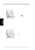
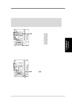
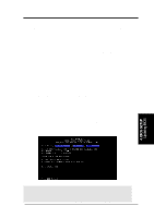
3. H/W SETUP Connectors 3. HARDWARE SETUP 21) Digital Audio Interface Header (2-pin SPDO/SPDI) only with Yamaha PCI audio This header is the digital link between the motherboard and your devices, such as CD player, sampler, or DAT recorder. It allows the digital transmission of audio data in SPDIF (Sony/Philips Digital Interface) format. CUWE-RM ® SPDO SPDO Signal GND SPDI SPDI Signal GND CUWE-RM Audio Digital Interface Connectors 22) Chassis Intrusion Lead (2-pin ACHA) This lead is for a chassis designed for chassis intrusion detection. After-market toggle switches may also be installed to the chassis panel or on any removable components. Two wires should be available from the chassis to connect to this lead. When any chassis component is removed, the circuit should open and the motherboard will record a chassis intrusion event. The event can then be processed by software such as LDCM. If the chassis intrusion lead is not used, a jumper cap must be placed over the pins to close the circuit. CUWE-RM ® ACHA CUWE-RM Chassis Open Alarm Lead 40 ASUS CUWE-RM User's Manual
-
 1
1 -
2
-
3
-
4
-
5
-
6
-
7
-
8
-
9
-
10
-
11
-
12
-
13
-
14
-
15
-
16
-
17
-
18
-
19
-
20
-
21
-
22
-
23
-
24
-
25
-
26
-
27
-
28
-
29
-
30
-
31
-
32
-
33
-
34
-
 35
35 -
 36
36 -
 37
37 -
 38
38 -
 39
39 -
 40
40 -
 41
41 -
 42
42 -
 43
43 -
 44
44 -
 45
45 -
46
-
47
-
48
-
49
-
50
-
51
-
52
-
53
-
54
-
55
-
56
-
57
-
58
-
59
-
60
-
61
-
62
-
63
-
64
-
65
-
66
-
67
-
68
-
69
-
70
-
71
-
72
-
73
-
74
-
75
-
76
-
77
-
78
-
79
-
80
-
81
-
82
-
83
-
84
-
85
-
86
-
87
-
88
-
89
-
90
-
91
-
92
-
93
-
94
-
95
-
96
-
97
-
98
-
99
-
100
-
101
-
102
-
103
-
104
-
105
-
106
-
107
-
108
-
109
-
110
-
111
-
112
-
113
-
114
-
115
-
116
-
117
-
118
-
119
-
120
-
121
-
122
-
123
-
124
-
125
-
126
-
127
-
128
-
129
-
130
-
131
-
132
-
133
-
134
 |
 |
