Asus CUWE-RM CUWE-RM User Manual - Page 42
CUWE-RM System Panel Connectors - driver cuw rm
 |
View all Asus CUWE-RM manuals
Add to My Manuals
Save this manual to your list of manuals |
Page 42 highlights
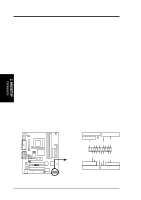
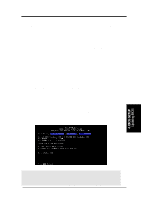
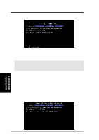
3. HARDWARE SETUP 25) System Power LED Lead (3-1 pin PLED) This 3-1 pin connector connects the system power LED, which lights when the system is powered on and blinks when it is in sleep mode. 26) Keyboard Lock Switch Lead (2-pin KEYLOCK) This 2-pin connector connects to the case-mounted key switch to allow keyboard locking. 27) System Warning Speaker Connector (4-pin SPEAKER) This 4-pin connector connects to the case-mounted speaker. 28) Reset Switch Lead (2-pin RESET) This 2-pin connector connects to the case-mounted reset switch for rebooting your computer without having to turn off your power switch. This is a preferred method of rebooting to prolong the life of the system's power supply. 29) ATX Power Switch Lead (2-pin PWR) The system power is controlled by a momentary switch connected to this lead. Pressing the button once will switch the system between ON and SOFT OFF. Pushing the switch while in the ON mode for more than 4 seconds will turn the system off. The system power LED shows the status of the system's power. 30) System Management Interrupt Lead (2-pin EXTSMI) This allows the user to manually place the system into a suspend mode or "Green" mode, where system activity is decreased to save electricity and expand the life of certain components when the system is not in use. This 2-pin connector connects to the case-mounted suspend switch. 31) Message LED Lead (2-pin LED) This indicates whether a message has been received from a fax/modem. The LED will remain lit when there is no signal and blink when there is data transfer or waiting in the inbox. This function requires ACPI OS and driver support. To enable ACPI support in Windows 98, reinstall Windows 98 using the command line setup /p j. Keyboard Lock Power LED Speaker Connector 3. H/W SETUP Connectors +5 V PLED Keylock Ground +5V Ground Ground SPKR +5 V MLED ExtSMI# Ground PWR_SW Ground ResetCon Ground CUWE-RM ® Message LED SMI Lead Reset SW ATX Power Switch* * Requires an ATX power supply. CUWE-RM System Panel Connectors 42 ASUS CUWE-RM User's Manual
-
 1
1 -
2
-
3
-
4
-
5
-
6
-
7
-
8
-
9
-
10
-
11
-
12
-
13
-
14
-
15
-
16
-
17
-
18
-
19
-
20
-
21
-
22
-
23
-
24
-
25
-
26
-
27
-
28
-
29
-
30
-
31
-
32
-
33
-
34
-
35
-
36
-
 37
37 -
 38
38 -
 39
39 -
 40
40 -
 41
41 -
 42
42 -
 43
43 -
 44
44 -
 45
45 -
 46
46 -
 47
47 -
48
-
49
-
50
-
51
-
52
-
53
-
54
-
55
-
56
-
57
-
58
-
59
-
60
-
61
-
62
-
63
-
64
-
65
-
66
-
67
-
68
-
69
-
70
-
71
-
72
-
73
-
74
-
75
-
76
-
77
-
78
-
79
-
80
-
81
-
82
-
83
-
84
-
85
-
86
-
87
-
88
-
89
-
90
-
91
-
92
-
93
-
94
-
95
-
96
-
97
-
98
-
99
-
100
-
101
-
102
-
103
-
104
-
105
-
106
-
107
-
108
-
109
-
110
-
111
-
112
-
113
-
114
-
115
-
116
-
117
-
118
-
119
-
120
-
121
-
122
-
123
-
124
-
125
-
126
-
127
-
128
-
129
-
130
-
131
-
132
-
133
-
134
 |
 |
