Asus DVD-E612 Manual - Page 8
Setting Your DVD-ROM Drive, Rear Panel Features
 |
View all Asus DVD-E612 manuals
Add to My Manuals
Save this manual to your list of manuals |
Page 8 highlights
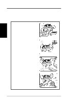
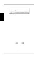
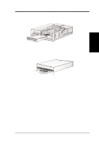
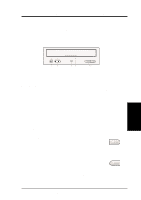
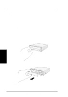
II. HARDWARE INSTALLATION Rear Panel Features CABLE SELECT DIGITAL ANALOG SLAVE AUDIO AUDIO MASTER IDE INTERFACE DG RGG L 39 40 POWER 1 +5V G G +12V 2 II. HardwareInstallaton ➁ ➀ D: Digital; G: Ground; R: Right audio channel; L: Left audio channel NOTE: The pin settings or definitions of the connectors and jumpers are also engraved on the Rear Panel of your DVD-ROM Drive. 1. Power Supply connector connects to the computer's power supply. 2. IDE Interface connector connects to the 40-pin interface cable. 3. Device configuration jumper allows you to set your DVD-ROM Drive as the Master or Slave drive. The default setting is Slave, wherein the jumper is on "SLAVE". "CABLE SELECT" is reserved and should not be used. 4. Analog Audio line out connector has two channels, right ("R") and left ("L") audio outputs, and allows you to direct audio output from your DVD-ROM Drive to your sound card when connected using a CD audio cable. "G" is for Ground. 5. Digital Audio output connector offers high quality audio effect by outputting digital signal to a D/A converter or for recording to a digital audio tape (DAT) or professional audio recording system. The connector follows the EBU-IEC958 standard set by the European Broadcast Union. 6. Testing jumpers are reserved for manufacturer's internal testing/diagnostic purposes. Setting Your DVD-ROM Drive Set your drive as either the Master or Slave (default) drive by placing the jumper cap on the desired jumper ¬. Slave Drive (Default) Master Drive NOTE: If your computer only allows you to connect a maximum of two devices and you have two hard disks, remove the Slave hard disk - you need the other IDE connector for your DVD-ROM Drive. If you only have one hard disk, set your DVD-ROM Drive as Slave. If your computer has two IDE connectors and two hard disks installed, either set your DVD-ROM Drive as Master on the secondary IDE connector or remove the Slave hard disk and replace it with your DVD-ROM Drive. Refer to your computer's manual for the system configuration and instructions on hardware installation. 8 ASUS High-Speed DVD-ROM Drive
-
 1
1 -
2
-
 3
3 -
 4
4 -
 5
5 -
 6
6 -
 7
7 -
 8
8 -
 9
9 -
 10
10 -
 11
11 -
 12
12 -
 13
13 -
14
-
15
-
16
-
17
-
18
-
19
-
20
-
21
-
22
-
23
-
24
-
25
-
26
-
27
-
28
-
29
-
30
 |
 |
