Asus E500 G5 SFF User Manual - Page 31
Card reader, USB3_12
 |
View all Asus E500 G5 SFF manuals
Add to My Manuals
Save this manual to your list of manuals |
Page 31 highlights
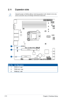
2.8 Card reader To install a card reader to the assembly module: 1. Remove the assembly module from the chassis. Refer to 2.6.1 Removing the assembly module for more information. 2. Insert and carefully push the card reader into the bay until its screw holes align with the holes on the bay. 3. Secure the card reader with two (2) screws into the screw holes on the right side of the assembly module, and one (1) screw on the left side of the assembly module. Screw holes 4. Connect the connector to the bundled USB 3.2 Gen 1 cable, then connect the USB 3.2 Gen 1 cable to the USB3_12 connector on the motherboard. Refer to section 3.5 Internal connectors for the location of the USB3_12 connector. ASUS E500 G5 SFF 2-13
-
 1
1 -
2
-
3
-
4
-
5
-
6
-
7
-
8
-
9
-
10
-
11
-
12
-
13
-
14
-
15
-
16
-
17
-
18
-
19
-
20
-
21
-
22
-
23
-
24
-
25
-
 26
26 -
 27
27 -
 28
28 -
 29
29 -
 30
30 -
 31
31 -
 32
32 -
 33
33 -
 34
34 -
 35
35 -
 36
36 -
37
-
38
-
39
-
40
-
41
-
42
-
43
-
44
-
45
-
46
-
47
-
48
-
49
-
50
-
51
-
52
-
53
-
54
-
55
-
56
-
57
-
58
-
59
-
60
-
61
-
62
-
63
-
64
-
65
-
66
-
67
-
68
-
69
-
70
-
71
-
72
-
73
-
74
-
75
-
76
-
77
-
78
-
79
-
80
-
81
-
82
-
83
-
84
-
85
-
86
-
87
-
88
-
89
-
90
-
91
-
92
-
93
-
94
-
95
-
96
-
97
-
98
-
99
-
100
-
101
-
102
-
103
-
104
-
105
-
106
-
107
-
108
-
109
-
110
-
111
-
112
-
113
-
114
-
115
-
116
-
117
-
118
-
119
-
120
-
121
-
122
-
123
-
124
-
125
-
126
-
127
-
128
-
129
-
130
-
131
-
132
-
133
-
134
-
135
-
136
-
137
-
138
-
139
-
140
-
141
-
142
 |
 |

2-13
ASUS E500 G5 SFF
2.8
Card reader
To install a card reader to the assembly module:
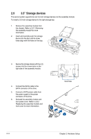
1.
Remove the assembly module from
the chassis. Refer to
2.6.1 Removing
the assembly module
for more
information.
2.
Insert and carefully push the card
reader into the bay until its screw
holes align with the holes on the bay.
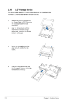
3.
Secure the card reader with two (2) screws into the screw holes on the right side of the
assembly module, and one (1) screw on the left side of the assembly module.
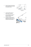
4.
Connect the connector to the bundled USB 3.2 Gen 1 cable, then connect the USB 3.2
Gen 1 cable to the
USB3_12
connector on the motherboard.
Refer to section
3.5 Internal connectors
for the location of the
USB3_12
connector.
Screw holes