Asus E500 G5 SFF User Manual - Page 33
Remove the assembly module from, for more information.
 |
View all Asus E500 G5 SFF manuals
Add to My Manuals
Save this manual to your list of manuals |
Page 33 highlights
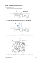
To install a 3.5-inch storage device to the left storage bay: 1. Remove the assembly module from the chassis. Refer to 2.6.1 Removing the assembly module for more information. 2. Insert and carefully push the storage device into the bay until its screw holes align with the holes on the bay. 3. Secure the storage device with four (4) screws into the screw holes shown in the illustration. Screw holes 4. Connect the SATA cable to the SATA connector of the drive. 5. Connect a SATA power cable from the power supply to the power connector of the drive. 6. Reinstall the assembly module and front panel cover. Refer to 2.6.2 Replacing the assembly module and front cover for more information. Screw holes ASUS E500 G5 SFF 2-15
-
 1
1 -
2
-
3
-
4
-
5
-
6
-
7
-
8
-
9
-
10
-
11
-
12
-
13
-
14
-
15
-
16
-
17
-
18
-
19
-
20
-
21
-
22
-
23
-
24
-
25
-
26
-
27
-
 28
28 -
 29
29 -
 30
30 -
 31
31 -
 32
32 -
 33
33 -
 34
34 -
 35
35 -
 36
36 -
 37
37 -
 38
38 -
39
-
40
-
41
-
42
-
43
-
44
-
45
-
46
-
47
-
48
-
49
-
50
-
51
-
52
-
53
-
54
-
55
-
56
-
57
-
58
-
59
-
60
-
61
-
62
-
63
-
64
-
65
-
66
-
67
-
68
-
69
-
70
-
71
-
72
-
73
-
74
-
75
-
76
-
77
-
78
-
79
-
80
-
81
-
82
-
83
-
84
-
85
-
86
-
87
-
88
-
89
-
90
-
91
-
92
-
93
-
94
-
95
-
96
-
97
-
98
-
99
-
100
-
101
-
102
-
103
-
104
-
105
-
106
-
107
-
108
-
109
-
110
-
111
-
112
-
113
-
114
-
115
-
116
-
117
-
118
-
119
-
120
-
121
-
122
-
123
-
124
-
125
-
126
-
127
-
128
-
129
-
130
-
131
-
132
-
133
-
134
-
135
-
136
-
137
-
138
-
139
-
140
-
141
-
142
 |
 |

2-15
ASUS E500 G5 SFF
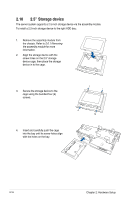
3.
Secure the storage device with four
(4) screws into the screw holes
shown in the illustration.
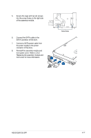
4.
Connect the SATA cable to the
SATA connector of the drive.
5.
Connect a SATA power cable from
the power supply to the power
connector of the drive.
6.
Reinstall the assembly module and
front panel cover. Refer to
2.6.2
Replacing the assembly module and
front cover
for more information.
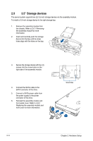
1.
Remove the assembly module from
the chassis. Refer to
2.6.1 Removing
the assembly module
for more
information.
2.
Insert and carefully push the storage
device into the bay until its screw
holes align with the holes on the bay.
To install a 3.5-inch storage device to the left storage bay:
Screw holes
Screw holes