Asus E900 G4 User Manual - Page 25
Apply the Thermal Interface Material to, into the socket to prevent damaging
 |
View all Asus E900 G4 manuals
Add to My Manuals
Save this manual to your list of manuals |
Page 25 highlights
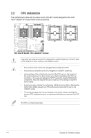
Triangle mark Apply the Thermal Interface Material to the CPU heatsink and CPU before you install the heatsink and fan, if necessary. The CPU and heatsink assembly fits in only one correct orientation. DO NOT force the CPU and heatsink assembly into the socket to prevent damaging the CPU pins on the socket. The heatsink screws are T30 models. A torque value of 12 inch-lbf is recommended. ASUS E900 G4 2-5
-
 1
1 -
2
-
3
-
4
-
5
-
6
-
7
-
8
-
9
-
10
-
11
-
12
-
13
-
14
-
15
-
16
-
17
-
18
-
19
-
 20
20 -
 21
21 -
 22
22 -
 23
23 -
 24
24 -
 25
25 -
 26
26 -
 27
27 -
 28
28 -
 29
29 -
 30
30 -
31
-
32
-
33
-
34
-
35
-
36
-
37
-
38
-
39
-
40
-
41
-
42
-
43
-
44
-
45
-
46
-
47
-
48
-
49
-
50
-
51
-
52
-
53
-
54
-
55
-
56
-
57
-
58
-
59
-
60
-
61
-
62
-
63
-
64
-
65
-
66
-
67
-
68
-
69
-
70
-
71
-
72
-
73
-
74
-
75
-
76
-
77
-
78
-
79
-
80
-
81
-
82
-
83
-
84
-
85
-
86
-
87
-
88
-
89
-
90
-
91
-
92
-
93
-
94
-
95
-
96
-
97
-
98
-
99
-
100
-
101
-
102
-
103
-
104
-
105
-
106
-
107
-
108
-
109
-
110
-
111
-
112
-
113
-
114
-
115
-
116
-
117
-
118
-
119
-
120
-
121
-
122
-
123
-
124
-
125
-
126
-
127
-
128
-
129
-
130
-
131
-
132
-
133
-
134
-
135
-
136
-
137
-
138
-
139
-
140
-
141
-
142
-
143
-
144
-
145
-
146
 |
 |

2-5
ASUS E900 G4
Triangle mark
Apply the Thermal Interface Material to
the CPU heatsink and CPU before you
install the heatsink and fan, if necessary.
The CPU and heatsink assembly fits in
only one correct orientation. DO NOT
force the CPU and heatsink assembly
into the socket to prevent damaging the
CPU pins on the socket.
The heatsink screws are T30 models.
A torque value of 12 inch-lbf is
recommended.