Asus E900 G4 User Manual - Page 47
Align the riser card with the screw holes on the riser card tray, then secure the riser
 |
View all Asus E900 G4 manuals
Add to My Manuals
Save this manual to your list of manuals |
Page 47 highlights
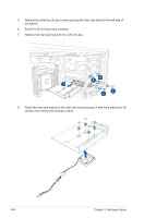
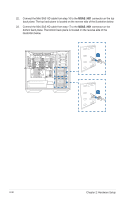
9. Align the riser card with the screw holes on the riser card tray, then secure the riser card to the tray using the bundled two (2) screws. Riser card tray screw holes 10. Connect the bundled power cable to the 4-pin power connector on the riser card. 11. Connect two (2) OCuLink cables to the riser card. OCUPCIE2 OCUPCIE1 ASUS E900 G4 2-27
-
 1
1 -
2
-
3
-
4
-
5
-
6
-
7
-
8
-
9
-
10
-
11
-
12
-
13
-
14
-
15
-
16
-
17
-
18
-
19
-
20
-
21
-
22
-
23
-
24
-
25
-
26
-
27
-
28
-
29
-
30
-
31
-
32
-
33
-
34
-
35
-
36
-
37
-
38
-
39
-
40
-
41
-
 42
42 -
 43
43 -
 44
44 -
 45
45 -
 46
46 -
 47
47 -
 48
48 -
 49
49 -
 50
50 -
 51
51 -
 52
52 -
53
-
54
-
55
-
56
-
57
-
58
-
59
-
60
-
61
-
62
-
63
-
64
-
65
-
66
-
67
-
68
-
69
-
70
-
71
-
72
-
73
-
74
-
75
-
76
-
77
-
78
-
79
-
80
-
81
-
82
-
83
-
84
-
85
-
86
-
87
-
88
-
89
-
90
-
91
-
92
-
93
-
94
-
95
-
96
-
97
-
98
-
99
-
100
-
101
-
102
-
103
-
104
-
105
-
106
-
107
-
108
-
109
-
110
-
111
-
112
-
113
-
114
-
115
-
116
-
117
-
118
-
119
-
120
-
121
-
122
-
123
-
124
-
125
-
126
-
127
-
128
-
129
-
130
-
131
-
132
-
133
-
134
-
135
-
136
-
137
-
138
-
139
-
140
-
141
-
142
-
143
-
144
-
145
-
146
 |
 |

2-27
ASUS E900 G4
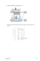
9.
Align the riser card with the screw holes on the riser card tray, then secure the riser
card to the tray using the bundled two (2) screws.
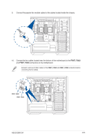
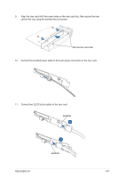
10.
Connect the bundled power cable to the 4-pin power connector on the riser card.
11.
Connect two (2) OCuLink cables to the riser card.
Riser card tray screw holes
OCUPCIE2
OCUPCIE1