Asus E900 G4 User Manual - Page 42
Thread the passive fan module cables through the passive fan module cable slot.
 |
View all Asus E900 G4 manuals
Add to My Manuals
Save this manual to your list of manuals |
Page 42 highlights
SPDIF OUT REAR C/SUB MIC IN LINE OUT LINE 5. Remove the metal cover of the passive fan module cable slot. Take extra care when removing the metal cover. Use tools such as a screw driver to bend and remove the metal cover to avoid physical injury. 6. Align the passive fan module to the screw holes around the expansion slots. The passive fan module is optional. 7. Thread the passive fan module cables through the passive fan module cable slot. 8. Secure the passive fan module to the chassis using the bundled screws. USB BIOS Flashback 10 USB3.1 TYPE C USB3.0 USB3.0 SPDIF OUT REAR C/SUB MIC IN LINE OUT LINE 2-22 Chapter 2: Hardware Setup
-
 1
1 -
2
-
3
-
4
-
5
-
6
-
7
-
8
-
9
-
10
-
11
-
12
-
13
-
14
-
15
-
16
-
17
-
18
-
19
-
20
-
21
-
22
-
23
-
24
-
25
-
26
-
27
-
28
-
29
-
30
-
31
-
32
-
33
-
34
-
35
-
36
-
 37
37 -
 38
38 -
 39
39 -
 40
40 -
 41
41 -
 42
42 -
 43
43 -
 44
44 -
 45
45 -
 46
46 -
 47
47 -
48
-
49
-
50
-
51
-
52
-
53
-
54
-
55
-
56
-
57
-
58
-
59
-
60
-
61
-
62
-
63
-
64
-
65
-
66
-
67
-
68
-
69
-
70
-
71
-
72
-
73
-
74
-
75
-
76
-
77
-
78
-
79
-
80
-
81
-
82
-
83
-
84
-
85
-
86
-
87
-
88
-
89
-
90
-
91
-
92
-
93
-
94
-
95
-
96
-
97
-
98
-
99
-
100
-
101
-
102
-
103
-
104
-
105
-
106
-
107
-
108
-
109
-
110
-
111
-
112
-
113
-
114
-
115
-
116
-
117
-
118
-
119
-
120
-
121
-
122
-
123
-
124
-
125
-
126
-
127
-
128
-
129
-
130
-
131
-
132
-
133
-
134
-
135
-
136
-
137
-
138
-
139
-
140
-
141
-
142
-
143
-
144
-
145
-
146
 |
 |

Chapter 2: Hardware Setup
2-22
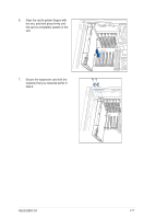
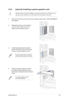
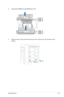
5.
Remove the metal cover of the passive fan
module cable slot.
Take extra care when removing the
metal cover. Use tools such as a screw
driver to bend and remove the metal
cover to avoid physical injury.
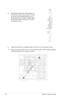
6.
Align the passive fan module to the screw holes around the expansion slots.
The passive fan module is optional.
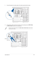
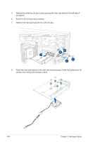
7.
Thread the passive fan module cables through the passive fan module cable slot.
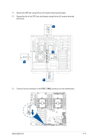
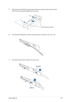
8.
Secure the passive fan module to the chassis using the bundled screws.