Asus H170-PRO User Guide - Page 12
Motherboard layout, Place this side, towards the rear, of the chassis - lga1151
 |
View all Asus H170-PRO manuals
Add to My Manuals
Save this manual to your list of manuals |
Page 12 highlights
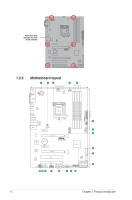
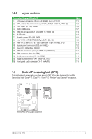
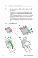
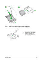
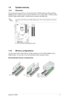
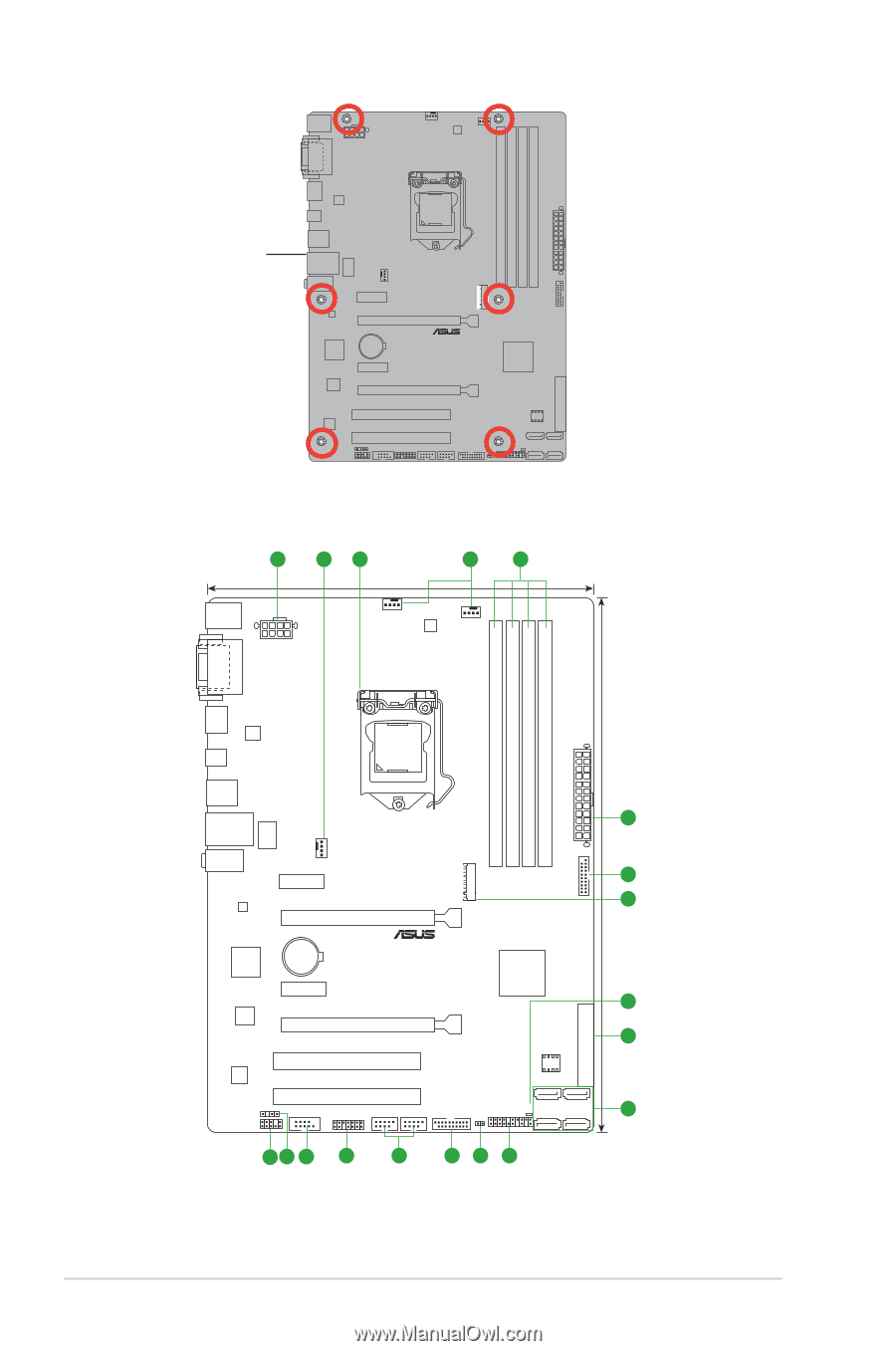
Place this side towards the rear of the chassis H170-PRO 1.2.3 Motherboard layout 1 2 3 2 4 22.4cm(8.8in) KBMS EATX12V CPU_FAN CHA_FAN1 DIGI +VRM DVI VGA DDR4 DIMM_A1 (64bit, 288-pin module) DDR4 DIMM_A2 (64bit, 288-pin module) DDR4 DIMM_B1 (64bit, 288-pin module) DDR4 DIMM_B2 (64bit, 288-pin module) EATXPWR 30.5cm(12in) HDMI ASM 1442K LGA1151 USB_C1 USB3_78 1 LAN_USB910 LANGuard M.2(SOCKET3) USB3_12 AUDIO CHA_FAN2 5 PCIEX1_1 6 RTL 8111H PCIEX16_1 ASM 1083 BATTERY H170-PRO Intel® H170 PCIEX1_2 7 Super I/O PCIEX16_2 8 SATAEXPRESS SATA6G_2 SATA6G_1 ALC 887 SPDIF_OUT AAFP PCI1 128Mb BIOS PCI2 COM TPM USB1112 USB1314 USB3_34 SATA6G_4 SATA6G_3 SB_PWR CLRTC PANEL SATA6G_6 SATA6G_5 9 16 15 14 13 12 5 11 10 1-2 Chapter 1: Product introduction
-
 1
1 -
2
-
3
-
4
-
5
-
6
-
 7
7 -
 8
8 -
 9
9 -
 10
10 -
 11
11 -
 12
12 -
 13
13 -
 14
14 -
 15
15 -
 16
16 -
 17
17 -
18
-
19
-
20
-
21
-
22
-
23
-
24
-
25
-
26
-
27
-
28
-
29
-
30
-
31
-
32
-
33
-
34
-
35
-
36
-
37
-
38
-
39
-
40
-
41
-
42
-
43
-
44
-
45
-
46
-
47
-
48
-
49
-
50
-
51
-
52
-
53
-
54
-
55
-
56
-
57
-
58
-
59
-
60
-
61
-
62
-
63
-
64
-
65
-
66
-
67
-
68
-
69
-
70
-
71
-
72
-
73
-
74
-
75
-
76
-
77
-
78
-
79
-
80
-
81
-
82
-
83
-
84
-
85
-
86
-
87
 |
 |
1-2
Chapter 1: Product introduction
Place this side
towards the rear
of the chassis
1.2.3
Motherboard layout
H170-PRO
H170-PRO
PCIEX16_1
PCIEX16_2
PCI1
PCI2
PCIEX1_2
PCIEX1_1
M.2(SOCKET3)
RTL
8111H
LANGuard
ASM
1442K
ASM
1083
USB1314
USB1112
AAFP
EATXPWR
BATTERY
Super
I/O
ALC
887
KBMS
DVI
VGA
CLRTC
22.4cm(8.8in)
DDR4 DIMM_A1 (64bit, 288-pin module)
DDR4 DIMM_A2 (64bit, 288-pin module)
DDR4 DIMM_B1 (64bit, 288-pin module)
DDR4 DIMM_B2 (64bit, 288-pin module)
LAN_USB910
USB_C1
HDMI
CHA_FAN2
CPU_FAN
CHA_FAN1
30.5cm(12in)
LGA1151
DIGI
+VRM
COM
SPDIF_OUT
EATX12V
USB3_34
USB3_12
128Mb
BIOS
SATAEXPRESS
SATA6G_1
SATA6G_2
PANEL
SB_PWR
AUDIO
SATA6G_6
SATA6G_5
SATA6G_4
SATA6G_3
Intel
®
H170
USB3_78
2
1
3
4
2
10
11
5
12
13
14
15
1
5
8
7
6
TPM
16
9