Asus L4R User Manual - Page 25
Front Side
 |
View all Asus L4R manuals
Add to My Manuals
Save this manual to your list of manuals |
Page 25 highlights
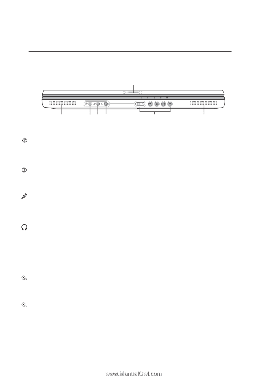
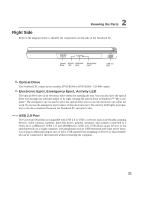
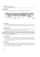
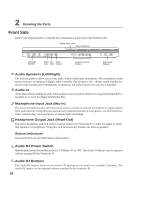
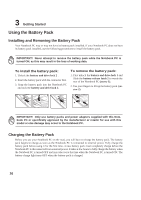
2 Knowing the Parts Front Side Refer to the diagram below to identify the components on this side of the Notebook PC. Display Panel Latch Status Indicators Left Audio Speaker Audio Mic Head Input Input Output Audio DJ Control Buttons Right Audio Speaker Audio Speakers (Left/Right) The built-in speakers allow you to hear audio without additional attachments. The multimedia sound system features an integrated digital audio controller that produces rich, vibrant sound (results improved with external stereo headphones or speakers). All audio features are software controlled. Audio In Audio input allows feeding in audio from another source in order to listen to it using the Notebook PC's speakers or to use it for digital multimedia files. Microphone Input Jack (Mic-In) The mono microphone jack (1/8 inch) can be used to connect an external microphone or output signals from audio devices. Using this jack automatically disables the built-in microphone. Use this feature for video conferencing, voice narrations, or simple audio recordings. Headphone Output Jack (Head-Out) The stereo headphone jack (1/8 inch) is used to connect the Notebook PC's audio out signal to amplified speakers or headphones. Using this jack automatically disables the built-in speakers. Status Indicators Status indicators are described later in this manual. Audio DJ Power Switch Slide the latch forward to turn the Audio DJ CD Player ON or OFF. The Audio DJ feature can be operated without turning ON the Notebook PC. Audio DJ Buttons The Audio DJ buttons allow you to control CD playing as you would on a portable CD player. The Audio DJ feature can be operated without turning ON the Notebook PC. 24
-
 1
1 -
2
-
3
-
4
-
5
-
6
-
7
-
8
-
9
-
10
-
11
-
12
-
13
-
14
-
15
-
16
-
17
-
18
-
19
-
 20
20 -
 21
21 -
 22
22 -
 23
23 -
 24
24 -
 25
25 -
 26
26 -
 27
27 -
 28
28 -
 29
29 -
 30
30 -
31
-
32
-
33
-
34
-
35
-
36
-
37
-
38
-
39
-
40
-
41
-
42
-
43
-
44
-
45
-
46
-
47
-
48
-
49
-
50
-
51
-
52
-
53
-
54
-
55
-
56
-
57
-
58
-
59
-
60
-
61
-
62
-
63
-
64
-
65
-
66
-
67
-
68
-
69
-
70
-
71
-
72
 |
 |