Asus MES-VM MES-VM User Manual - Page 29
System Power LED Lead 3-1 pin PWR.LED
 |
View all Asus MES-VM manuals
Add to My Manuals
Save this manual to your list of manuals |
Page 29 highlights
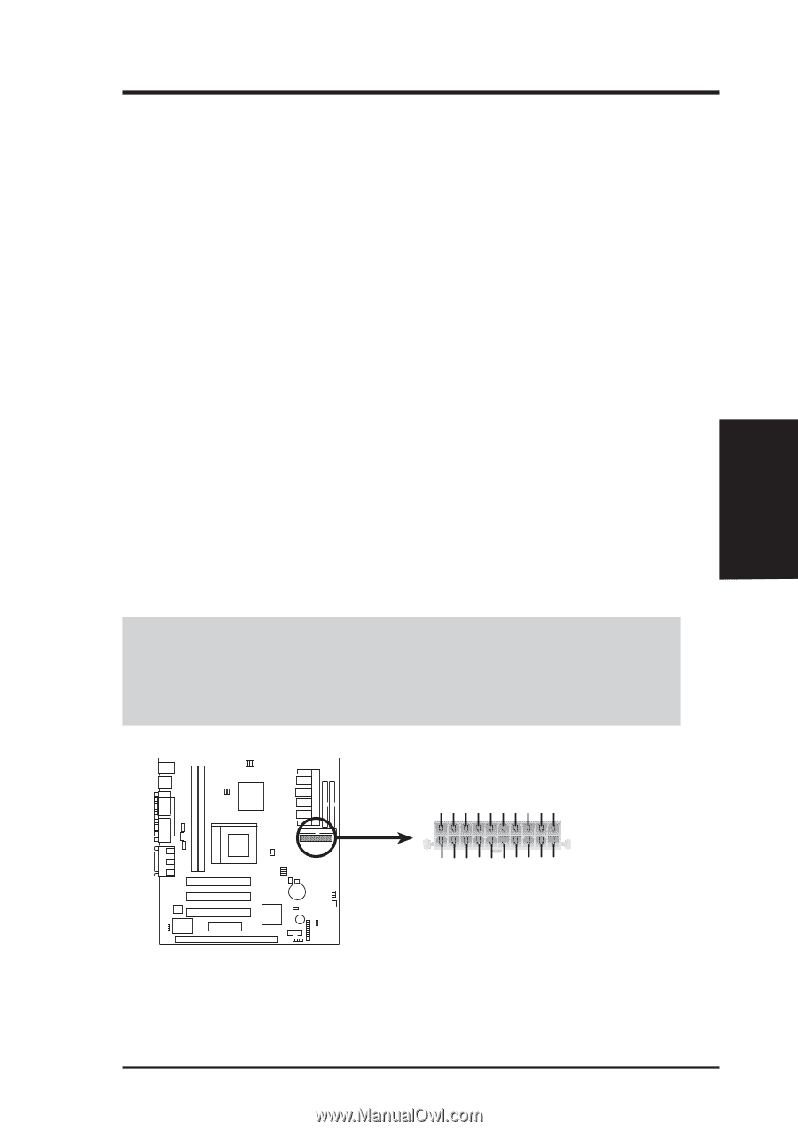
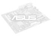
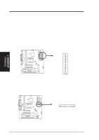
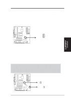
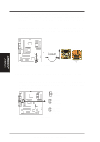
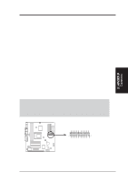
3. HARDWARE SETUP 19) Reset Switch Lead (2-pin RESET) This 2-pin connector connects to the case-mounted reset switch for rebooting your computer without having to turn off your power switch. This is a preferred method of rebooting to prolong the life of the system's power supply. 20) System Power LED Lead (3-1 pin PWR.LED) This 3-1 pin connector connects the system power LED, which lights when the system is powered on and blinks when it is in sleep mode. 21) ATX Power Switch Lead (2-pin PWR.SW) The system power is controlled by a momentary switch connected to this lead. Pressing the button once will switch the system between ON and SOFT OFF. Pushing the switch while in the ON mode for more than 4 seconds will turn the system off. The system power LED shows the status of the system's power. 22) Hard Disk Activity LED Lead (2-pin IDELED) This connector supplies power to the cabinet's hard disk or IDE activity LED. Read and write activity by devices connected to the Primary and/or Secondary IDE connectors will cause the LED to light up. 23) ATX Power Supply Connector (20-pin block ATXPWR) This connector connects to an ATX power supply. The plug from the power supply will only insert in one orientation because of the different hole sizes. Find the proper orientation and push down firmly making sure that the pins are aligned. IMPORTANT: Make sure that your ATX power supply can supply at least 10mA on the +5-volt standby lead (+5VSB). You may experience difficulty in powering ON your system if your power supply cannot support the load. For WakeOn-LAN support, your ATX power supply must supply at least 720mA +5VSB. 3. H/W SETUP Connectors +3.3 Volts +3.3 Volts Ground +5.0 Volts Ground +5.0 Volts Ground Power Good +5V Standby +12.0 Volts +3.3 Volts -12.0 Volts Ground Power Supply On Ground Ground Ground -5.0 Volts +5.0 Volts +5.0 Volts MES-VM ATX Power Connector ASUS MES-VM User's Manual 29
-
 1
1 -
2
-
3
-
4
-
5
-
6
-
7
-
8
-
9
-
10
-
11
-
12
-
13
-
14
-
15
-
16
-
17
-
18
-
19
-
20
-
21
-
22
-
23
-
 24
24 -
 25
25 -
 26
26 -
 27
27 -
 28
28 -
 29
29 -
 30
30 -
 31
31 -
 32
32 -
 33
33 -
 34
34 -
35
-
36
-
37
-
38
-
39
-
40
-
41
-
42
-
43
-
44
-
45
-
46
-
47
-
48
-
49
-
50
-
51
-
52
-
53
-
54
-
55
-
56
-
57
-
58
-
59
-
60
-
61
-
62
-
63
-
64
-
65
-
66
-
67
-
68
-
69
-
70
-
71
-
72
-
73
-
74
-
75
-
76
-
77
-
78
-
79
-
80
-
81
-
82
-
83
-
84
-
85
-
86
-
87
-
88
 |
 |