Asus NCL-D User Manual - Page 25
for illustration.
 |
View all Asus NCL-D manuals
Add to My Manuals
Save this manual to your list of manuals |
Page 25 highlights
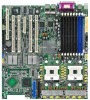
6. Before installing the motherboard into the chassis, locate the standoffs that should match the eight (8) CEK spring screw holes. Standoffs for CPU1 Standoffs for CPU2 7. Install the motherboard with the external I/O ports toward the chassis rear panel. The CPU sockets should be right on top of their respective standoffs. Socket for CPU1 Socket for CPU2 Make sure that the standoffs perfectly match the CEK spring screw holes; otherwise, you can not install the CPU heatsinks properly. 8. Secure the motherboard with 9 screws. Refer to section "2.2.2 Screw holes" for illustration. ASUS NCL-DE Series 2-5
-
 1
1 -
2
-
3
-
4
-
5
-
6
-
7
-
8
-
9
-
10
-
11
-
12
-
13
-
14
-
15
-
16
-
17
-
18
-
19
-
 20
20 -
 21
21 -
 22
22 -
 23
23 -
 24
24 -
 25
25 -
 26
26 -
 27
27 -
 28
28 -
 29
29 -
 30
30 -
31
-
32
-
33
-
34
-
35
-
36
-
37
-
38
-
39
-
40
-
41
-
42
-
43
-
44
-
45
-
46
-
47
-
48
-
49
-
50
-
51
-
52
-
53
-
54
-
55
-
56
-
57
-
58
-
59
-
60
-
61
-
62
-
63
-
64
-
65
-
66
-
67
-
68
-
69
-
70
-
71
-
72
-
73
-
74
-
75
-
76
-
77
-
78
-
79
-
80
-
81
-
82
-
83
-
84
-
85
-
86
-
87
-
88
-
89
-
90
-
91
-
92
-
93
-
94
-
95
-
96
-
97
-
98
-
99
-
100
-
101
-
102
-
103
-
104
-
105
-
106
-
107
-
108
-
109
-
110
-
111
-
112
-
113
-
114
-
115
-
116
-
117
-
118
-
119
-
120
-
121
-
122
-
123
-
124
-
125
-
126
-
127
-
128
-
129
-
130
-
131
-
132
-
133
-
134
-
135
-
136
-
137
-
138
-
139
-
140
-
141
-
142
-
143
-
144
-
145
-
146
-
147
-
148
-
149
-
150
-
151
-
152
-
153
-
154
-
155
-
156
-
157
-
158
-
159
-
160
-
161
-
162
-
163
-
164
-
165
-
166
-
167
-
168
-
169
-
170
-
171
-
172
-
173
-
174
-
175
-
176
 |
 |

ASUS
ASUS
ASUS
ASUS
ASUS NCL-DE
NCL-DE
NCL-DE
NCL-DE
NCL-DE Series
Series
Series
Series
Series
2-5
2-5
2-5
2-5
2-5
6.
Before installing the
motherboard into the chassis,
locate the standoffs that should
match the eight (8) CEK spring
screw holes.
8.
Secure the motherboard with 9 screws. Refer to section
“
2.2.2 Screw
holes
”
for illustration.
Make sure that the standoffs perfectly match the CEK spring screw
holes; otherwise, you can not install the CPU heatsinks properly.
7.
Install the motherboard with the
external I/O ports toward the
chassis rear panel. The CPU
sockets should be right on top
of their respective standoffs.
Standoffs for CPU1
Standoffs for CPU1
Standoffs for CPU1
Standoffs for CPU1
Standoffs for CPU1
Standoffs for CPU2
Standoffs for CPU2
Standoffs for CPU2
Standoffs for CPU2
Standoffs for CPU2
Socket for CPU1
Socket for CPU1
Socket for CPU1
Socket for CPU1
Socket for CPU1
Socket for CPU2
Socket for CPU2
Socket for CPU2
Socket for CPU2
Socket for CPU2