Asus P I-P6NP5 User Manual - Page 10
Iii. Installation
 |
View all Asus P I-P6NP5 manuals
Add to My Manuals
Save this manual to your list of manuals |
Page 10 highlights
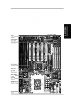
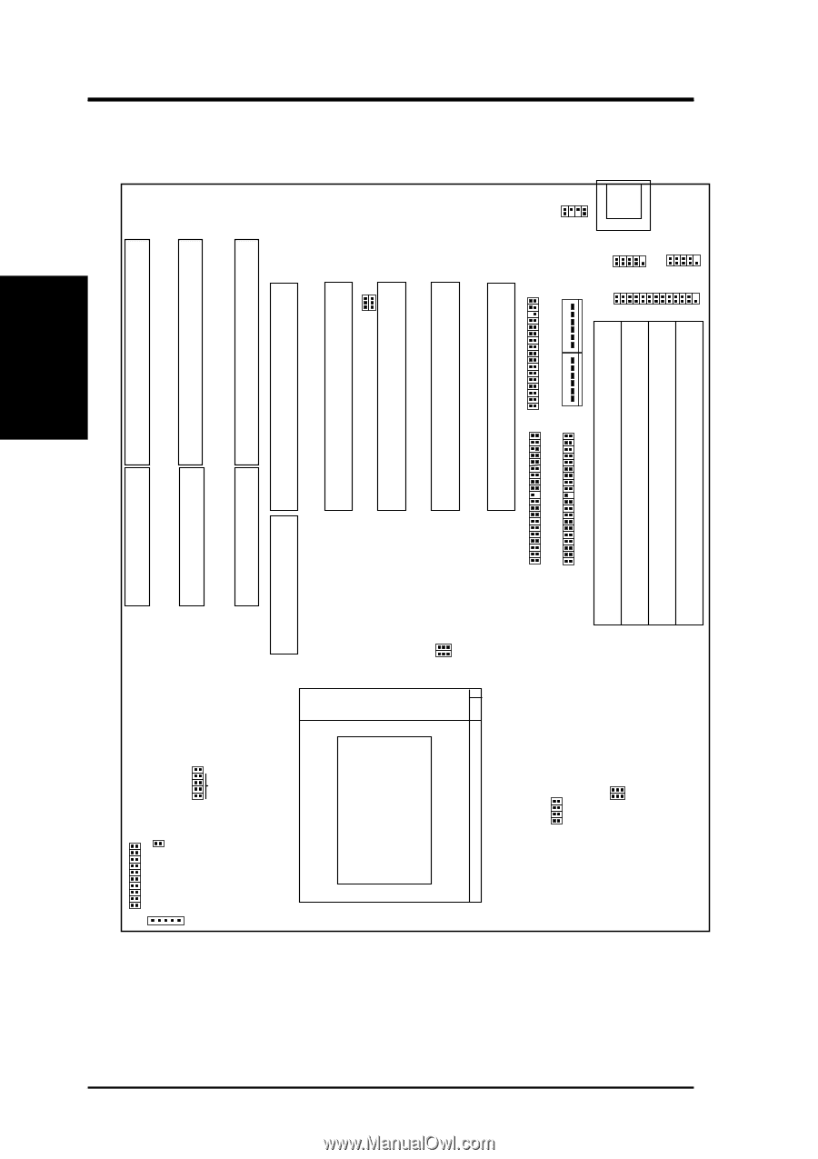
III. INSTALLATION Map of the Motherboard PS/2 Mouse Keyboard COM 1 COM 2 Parallel Printer SIMM Slot 4 (Bank 1) SIMM Slot 3 (Bank 1) SIMM Slot 2 (Bank 0) SIMM Slot 1 (Bank 0) Board Power Input Primary IDE P9 P8 Floppy Drives Secondary IDE PCI Slot 1 PCI Slot 2 PCI Slot 3 JP10 JP13 Multi I/O ROM Program PCI Slot 4 PCI Slot 5 / MediaBus 2.0 ISA Slot 1 ISA Slot 2 ISA Slot 3 III. INSTALLATION (Map of Board) JP2 JP3 BUS Freq. ZIF Socket 8 JP12 JP5 JP7 JP6 JP4 CMOS RAM CPU:BUS Ratio JP1 JP15 JP16 JP17 JP18 Voltage Regulator Fan Power IDE LED Case Connections Infrared 4 P/I-P6NP5 User's Manual
-
 1
1 -
2
-
3
-
4
-
 5
5 -
 6
6 -
 7
7 -
 8
8 -
 9
9 -
 10
10 -
 11
11 -
 12
12 -
 13
13 -
 14
14 -
 15
15 -
16
-
17
-
18
-
19
-
20
-
21
-
22
-
23
-
24
-
25
-
26
-
27
-
28
-
29
-
30
-
31
-
32
-
33
-
34
-
35
-
36
-
37
-
38
-
39
-
40
-
41
-
42
-
43
-
44
-
45
-
46
-
47
-
48
-
49
-
50
-
51
-
52
-
53
-
54
-
55
-
56
-
57
-
58
-
59
-
60
-
61
-
62
-
63
-
64
 |
 |
P/I-P6NP5 User's Manual
4
III. INSTALLATION
Map of the Motherboard
(Map of Board)
III.
INSTALLATION
ISA Slot 3
ISA Slot 2
ISA Slot 1
PCI Slot 5 / MediaBus 2.0
PCI Slot 3
PCI Slot 2
PCI Slot 1
SIMM Slot 1 (Bank 0)
SIMM Slot 2 (Bank 0)
SIMM Slot 3 (Bank 1)
SIMM Slot 4 (Bank 1)
ZIF Socket 8
Keyboard
Infrared
Case Connections
PCI Slot 4
PS/2
Mouse
JP13
JP10
JP12
JP5
JP7
JP6
JP4
JP2
JP3
JP15
JP16
JP17
JP18
Fan Power
Parallel Printer
COM 1
COM 2
Floppy Drives
Primary IDE
Secondary IDE
P9
Board Power Input
P8
ROM Program
Multi I/O
BUS Freq.
JP1
Voltage Regulator
IDE LED
CMOS RAM
CPU:BUS Ratio