Asus P I-P6NP5 User Manual - Page 28
Turbo LED switch CON1
 |
View all Asus P I-P6NP5 manuals
Add to My Manuals
Save this manual to your list of manuals |
Page 28 highlights
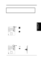
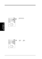
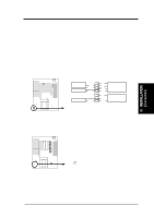
III. INSTALLATION 7. Primary / Secondary IDE connectors (Two 40-pin Block) This connector supports the provided IDE hard disk ribbon cable. After connecting the single end to the board, connect the two plugs at the other end to your hard disk(s). If you install two hard disks, you must configure the second drive to Slave mode by setting its jumpers accordingly. Please refer to the documentation of your hard disk for the jumper settings. You may also configure two hard disks to be both Masters using one ribbon cable on the primary IDE connector and another ribbon cable on the secondary IDE connector. (Pin 20 is removed to prevent inserting in the wrong orientation when using ribbon cables with pin 20 plugged). Pin 1 III. INSTALLATION (Connectors) Primary IDE Connector Secondary IDE Connector 8. Turbo LED switch (CON1) The motherboard's turbo function is always on. The turbo LED connection is labeled here but the LED will remain constantly lit while the system power is on. You may wish to connect the Power LED from the system case to this lead. (See the figure on the next page) 9. SMI suspend switch lead (CON1) This allows the user to manually place the system into a suspend mode or "Green" mode where system activity will be instantly decreased to save electricity and expand the life of certain components when the system is not in use. This 2-pin connector (See the figure on the next page) connects to the case-mounted suspend switch. If you do not have a switch for the connector, you may use the "Turbo Switch" since it does not have a function. SMI is activated when it detects a short to open moment and therefore leaving it shorted will not cause any problems. May require one or two pushes depending on the position of the switch. Wake-up can be controlled by settings in the BIOS but the keyboard will always allow wake-up (the SMI lead cannot wake-up the system). If you want to use this connector, "Suspend Switch" in the POWER MANAGEMENT SETUP of the BIOS software should be on the default setting of Enable. 22 P/I-P6NP5 User's Manual
-
 1
1 -
2
-
3
-
4
-
5
-
6
-
7
-
8
-
9
-
10
-
11
-
12
-
13
-
14
-
15
-
16
-
17
-
18
-
19
-
20
-
21
-
22
-
 23
23 -
 24
24 -
 25
25 -
 26
26 -
 27
27 -
 28
28 -
 29
29 -
 30
30 -
 31
31 -
 32
32 -
 33
33 -
34
-
35
-
36
-
37
-
38
-
39
-
40
-
41
-
42
-
43
-
44
-
45
-
46
-
47
-
48
-
49
-
50
-
51
-
52
-
53
-
54
-
55
-
56
-
57
-
58
-
59
-
60
-
61
-
62
-
63
-
64
 |
 |
