Asus P I-P6NP5 User Manual - Page 29
P/I-P6NP5 User's Manual, Reset switch lead CON1, Keyboard lock switch lead CON1, Speaker connector
 |
View all Asus P I-P6NP5 manuals
Add to My Manuals
Save this manual to your list of manuals |
Page 29 highlights
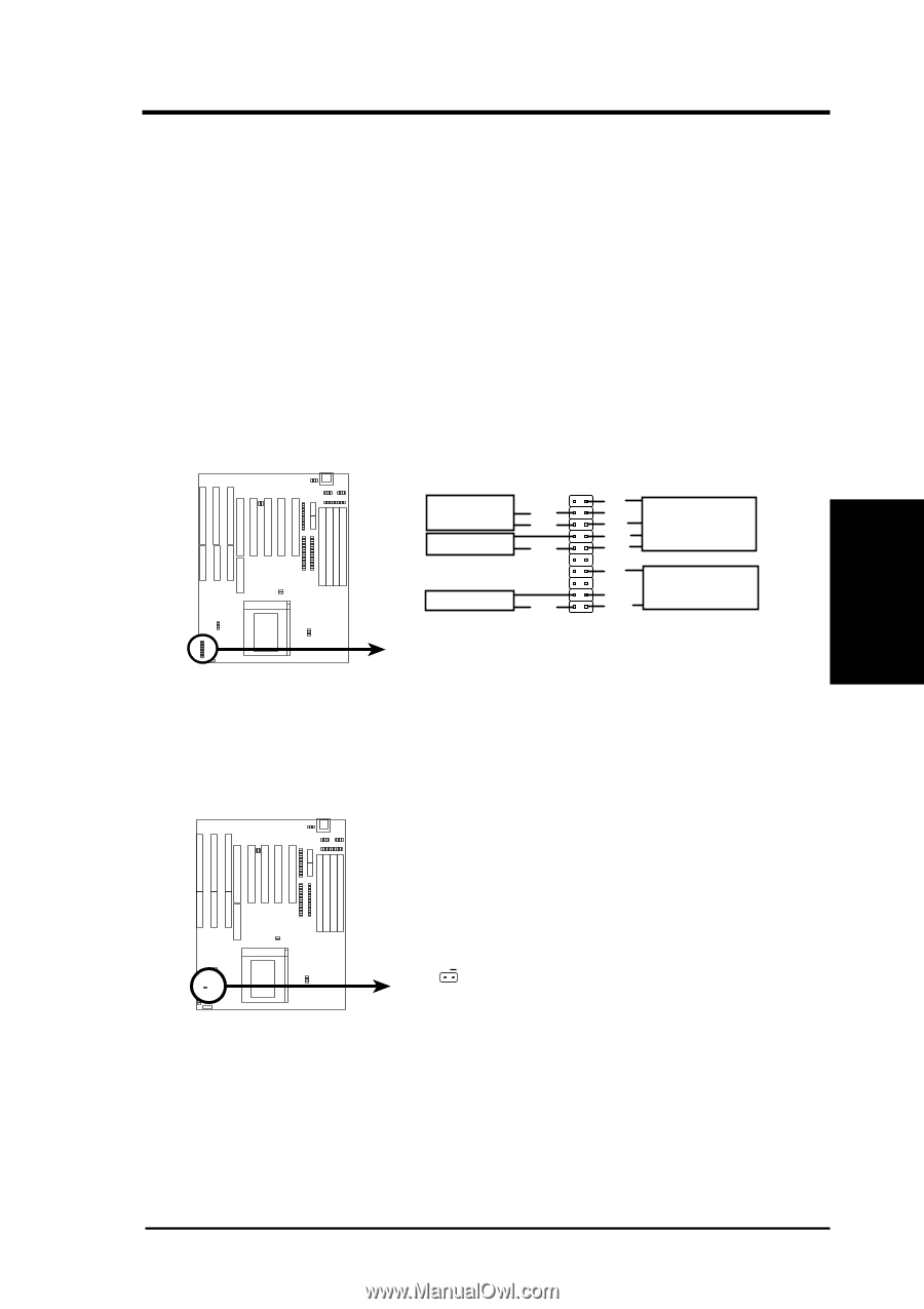
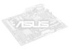
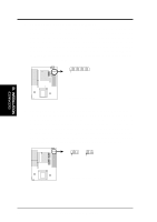
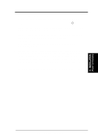
III. INSTALLATION (Connectors) III. INSTALLATION 10. Reset switch lead (CON1) This 2-pin connector connects to the case-mounted reset switch for rebooting your computer without having to turn off your power switch This is a preferred method of rebooting in order to prolong the life of the system's power supply. See the figure below. 11. Keyboard lock switch lead (CON1) This 5-pin connector connects to the case-mounted key switch for locking the keyboard for security purposes. See the figure below. 12. Speaker connector (CON1) This 4-pin connector connects to the case-mounted speaker. Turbo or Power LED +5V GND SMI Lead GND Reset SW GND +5V NC Power LED & GND LOCK Keyboard Lock GND +5V Speaker GND Connector SPKR System Case Connections 13. IDE activity LED (IDE_LED) This connector connects to the hard disk activity indicator light on the system cabinet. IDE_LED + IDE Activity LED P/I-P6NP5 User's Manual 23
-
 1
1 -
2
-
3
-
4
-
5
-
6
-
7
-
8
-
9
-
10
-
11
-
12
-
13
-
14
-
15
-
16
-
17
-
18
-
19
-
20
-
21
-
22
-
23
-
 24
24 -
 25
25 -
 26
26 -
 27
27 -
 28
28 -
 29
29 -
 30
30 -
 31
31 -
 32
32 -
 33
33 -
 34
34 -
35
-
36
-
37
-
38
-
39
-
40
-
41
-
42
-
43
-
44
-
45
-
46
-
47
-
48
-
49
-
50
-
51
-
52
-
53
-
54
-
55
-
56
-
57
-
58
-
59
-
60
-
61
-
62
-
63
-
64
 |
 |