Asus P2B-F P2B-F User Manual - Page 17
System Memory DIMM - cpu support
 |
View all Asus P2B-F manuals
Add to My Manuals
Save this manual to your list of manuals |
Page 17 highlights
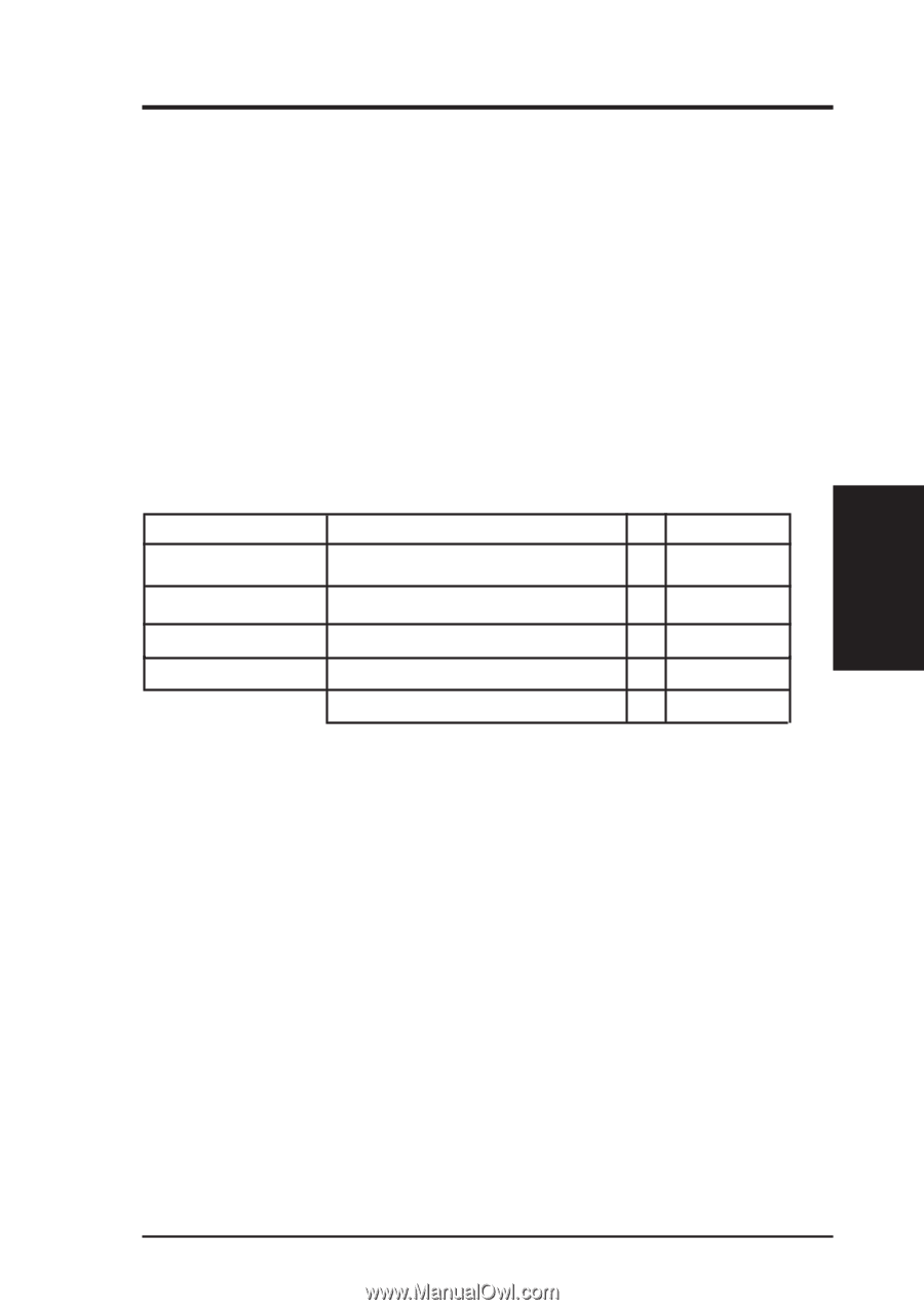
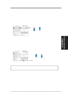
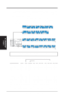
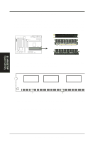
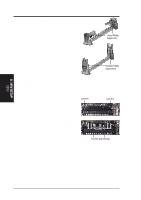
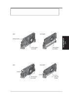
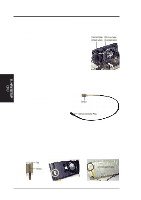
III. H/W SETUP System Memory III. HARDWARE SETUP 2. System Memory (DIMM) NOTE: No hardware or BIOS setup is required after adding or removing memory. This motherboard uses only Dual Inline Memory Modules (DIMMs). Sockets are available for 3.3Volt (power level) unbuffered Synchronous Dynamic Random Access Memory (SDRAM). One side (with memory chips) of the DIMM takes up one row on the motherboard. To utilize the chipset's Error Checking and Correction (ECC) feature, you must use a DIMM module with 9 chips per side (standard 8 chips/side + 1 ECC chip) and make the proper settings through Chipset Features Setup in BIOS SETUP. Memory speed setup is recommended through SDRAM Configuration under "Chipset Features Setup" in BIOS SETUP. Install memory in any combination as follows: DIMM Location 168-pin DIMM Total Memory Socket 1 (Rows 0&1) SDRAM 8, 16, 32, 64, 128, 256MB x1 Socket 2 (Rows 2&3) SDRAM 8, 16, 32, 64, 128, 256MB x1 Socket 3 (Rows 4&5) SDRAM 8, 16, 32, 64, 128, 256MB x1 Socket 4 (Rows 6&7) SDRAM 8, 16, 32, 64, 128, 256MB x1 Total System Memory (Max 1024MB) = General DIMM Notes • For the system CPU bus to operate at 100MHz, use only PC100-compliant DIMMs. When this motherboard operates at 100MHz, most system will not even boot if non-compliant modules are used because of the strict timing issues involved under this speed. If your DIMMs are not PC100-compliant, set the CPU bus frequency to 66MHz RAM to ensure system stability. • ASUS motherboards support SPD (Serial Presence Detect) DIMMs. This is the memory of choice for best performance vs. stability. • Two possible memory chips are supported: SDRAM with and without ECC. • SDRAM chips are generally thinner with higher pin density than EDO (Extended Data Output) chips. • BIOS shows SDRAM memory on bootup screen. • 8 chips/side modules do not support ECC, only 9 chips/side modules support ECC. • Single-sided DIMMs come in 16, 32, 64,128MB; double-sided come in 32, 64, 128, 256MB. ASUS P2B-F User's Manual 17
-
 1
1 -
2
-
3
-
4
-
5
-
6
-
7
-
8
-
9
-
10
-
11
-
 12
12 -
 13
13 -
 14
14 -
 15
15 -
 16
16 -
 17
17 -
 18
18 -
 19
19 -
 20
20 -
 21
21 -
 22
22 -
23
-
24
-
25
-
26
-
27
-
28
-
29
-
30
-
31
-
32
-
33
-
34
-
35
-
36
-
37
-
38
-
39
-
40
-
41
-
42
-
43
-
44
-
45
-
46
-
47
-
48
-
49
-
50
-
51
-
52
-
53
-
54
-
55
-
56
-
57
-
58
-
59
-
60
-
61
-
62
-
63
-
64
-
65
-
66
-
67
-
68
-
69
-
70
-
71
-
72
-
73
-
74
-
75
-
76
-
77
-
78
-
79
-
80
 |
 |