Asus P2B-F P2B-F User Manual - Page 27
Serial Port COM1 and COM2 Connectors Two 9-pin male
 |
View all Asus P2B-F manuals
Add to My Manuals
Save this manual to your list of manuals |
Page 27 highlights
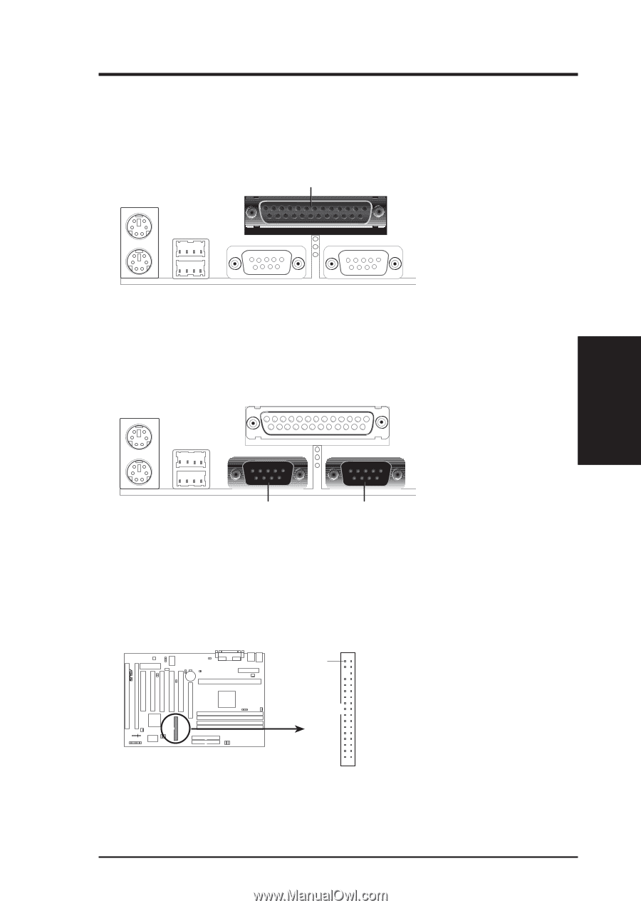
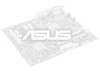
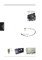
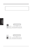
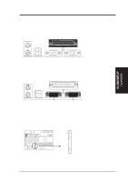
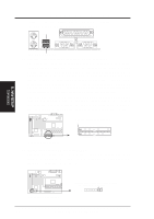
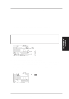
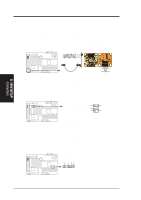
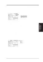
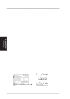
III. HARDWARE SETUP 3. Parallel Port Connector (25-pin female) You can enable the parallel port and choose the IRQ through "Onboard Parallel Port" in Chipset Features Setup of the BIOS SETUP. NOTE: Serial printers must be connected to the serial port. Parallel (Printer) Port (25-pin Female) 4. Serial Port COM1 and COM2 Connectors (Two 9-pin male) The two serial ports can be used for pointing devices or other serial devices. See "Onboard Serial Port" in Chipset Features Setup of the BIOS SETUP. III. H/W SETUP D CMoAnCnhecatnonrsels COM 1 COM 2 Serial Ports (9-pin Male) 5. Floppy Disk Drive Connector (34-1pin FLOPPY) This connector supports the provided floppy disk drive ribbon cable. After connecting the single end to the board, connect the two plugs on the other end to the floppy drives. (Pin 5 is removed to prevent inserting in the wrong orientation when using ribbon cables with pin 5 plugged). Pin 1 NOTE: Orient the red stripe to Pin 1 R Floppy Drive Connector P2B-F Floppy Disk Drive Connector ASUS P2B-F User's Manual 27
-
 1
1 -
2
-
3
-
4
-
5
-
6
-
7
-
8
-
9
-
10
-
11
-
12
-
13
-
14
-
15
-
16
-
17
-
18
-
19
-
20
-
21
-
 22
22 -
 23
23 -
 24
24 -
 25
25 -
 26
26 -
 27
27 -
 28
28 -
 29
29 -
 30
30 -
 31
31 -
 32
32 -
33
-
34
-
35
-
36
-
37
-
38
-
39
-
40
-
41
-
42
-
43
-
44
-
45
-
46
-
47
-
48
-
49
-
50
-
51
-
52
-
53
-
54
-
55
-
56
-
57
-
58
-
59
-
60
-
61
-
62
-
63
-
64
-
65
-
66
-
67
-
68
-
69
-
70
-
71
-
72
-
73
-
74
-
75
-
76
-
77
-
78
-
79
-
80
 |
 |