Asus P3C2000 P3C20000 User Manual - Page 44
I/O Device Configuration, 5.1 Power Up Control
 |
View all Asus P3C2000 manuals
Add to My Manuals
Save this manual to your list of manuals |
Page 44 highlights
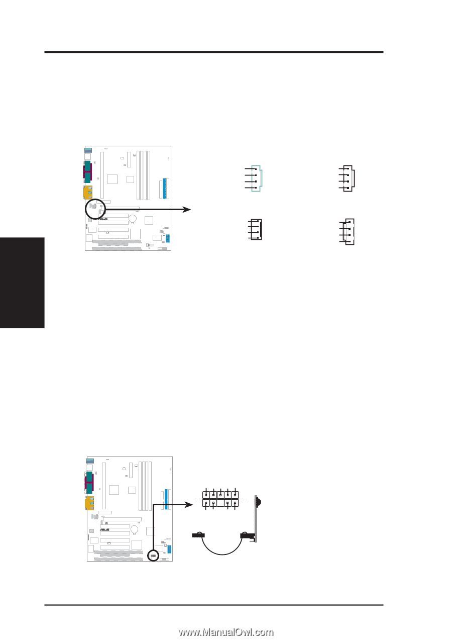
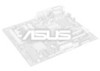
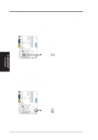
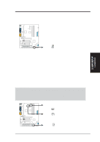
3. HARDWARE SETUP 15) Internal Audio Connectors (4-pin CD_IN, AUX, VIDEO, MODEM) These connectors allow you to receive stereo audio input from such sound sources as a CD-ROM, TV tuner, or MPEG card. The MODEM connector allows the onboard audio to interface with a voice modem card with a similar connector. It also allows the sharing of mono_in (such as a phone) and mono_out (such as a speaker) between the onboard audio and a voice modem card. VIDEO (GREEN) Right Audio Channel Ground Ground Left Audio Channel 3 0 P3C2000 ® MODEM Modem-In Ground Ground Modem-Out P3C2000 Internal Audio Connectors CD_IN (BLACK) Right Audio Channel Ground Ground Left Audio Channel AUX (WHITE) Left Audio Channel Ground Ground Right Audio Channel 16) Serial and Consumer Infrared Module Connector (10-pin IR) This connector supports an optional wireless transmitting and receiving infrared module. This module mounts to a small opening on system cases that support this feature. You must also configure the setting through UART2 Use Infrared (see 4.4.2 I/O Device Configuration) to select whether UART2 is directed for use with COM2 or IrDA. Use the five pins as shown in Back View and connect a ribbon cable from the module to the motherboard's SIR connector according to the pin definitions. An optional consumer infrared (CIR) set connects to the CIR and SIR connectors simultaneously for both wireless transmitting and remote control functions through one external infrared module. Wake On PS2 KB/Mouse in 4.5.1 Power Up Control must be Enabled in order to use Consumer Infrared (CIR) power up. 3. H/W SETUP Connectors +5V (NC) IRRX GND IRTX 3 0 P3C2000 ® (NC) GND CIRRX CIR+5V SIR CIR P3C2000 Infrared Module Connector 44 ASUS P3C2000 User's Manual
-
 1
1 -
2
-
3
-
4
-
5
-
6
-
7
-
8
-
9
-
10
-
11
-
12
-
13
-
14
-
15
-
16
-
17
-
18
-
19
-
20
-
21
-
22
-
23
-
24
-
25
-
26
-
27
-
28
-
29
-
30
-
31
-
32
-
33
-
34
-
35
-
36
-
37
-
38
-
 39
39 -
 40
40 -
 41
41 -
 42
42 -
 43
43 -
 44
44 -
 45
45 -
 46
46 -
 47
47 -
 48
48 -
 49
49 -
50
-
51
-
52
-
53
-
54
-
55
-
56
-
57
-
58
-
59
-
60
-
61
-
62
-
63
-
64
-
65
-
66
-
67
-
68
-
69
-
70
-
71
-
72
-
73
-
74
-
75
-
76
-
77
-
78
-
79
-
80
-
81
-
82
-
83
-
84
-
85
-
86
-
87
-
88
-
89
-
90
-
91
-
92
-
93
-
94
-
95
-
96
-
97
-
98
-
99
-
100
-
101
-
102
-
103
-
104
-
105
-
106
-
107
-
108
-
109
-
110
 |
 |