Asus P4B-LS Motherboard DIY Troubleshooting Guide - Page 32
System memory
 |
View all Asus P4B-LS manuals
Add to My Manuals
Save this manual to your list of manuals |
Page 32 highlights
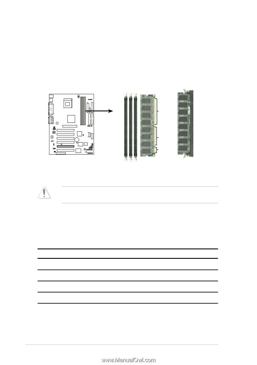
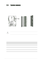
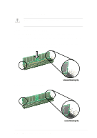
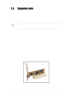
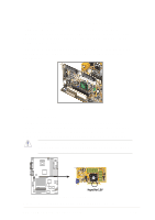
2.5 System memory 2.5.1 Overview The motherboard comes with three Single Data Rate (SDR) Dual Inline Memory Module (DIMM) sockets. These sockets support up to 3GB system memory using unbuffered ECC or non-ECC PC100/133 DIMMs. 88 Pins ® P4B-LS 60 Pins P4B-LS 168-Pin DIMM Sockets 20 Pins Figure 2-13 DIMM Sockets Location and SDR DIMMs DIMMs are keyed with notches so that they fit in only one direction. DO NOT force a DIMM into a socket to avoid damaging the DIMM. 2.5.2 Memory configurations Install DIMMs in any of the following combinations. DIMM Location 168-pin DIMM (SDR) Total Memory Socket 1 (Rows 0&1) 64MB, 128MB, 256MB, 512MB, 1GB x1 Socket 2 (Rows 2&3) 64MB, 128MB, 256MB, 512MB, 1GB x1 Socket 3 (Rows 4&5) 64MB, 128MB, 256MB, 512MB, 1GB x1 Total system memory (Max. 3GB) = 2-10 Chapter 2: Hardware information
-
 1
1 -
2
-
3
-
4
-
5
-
6
-
7
-
8
-
9
-
10
-
11
-
12
-
13
-
14
-
15
-
16
-
17
-
18
-
19
-
20
-
21
-
22
-
23
-
24
-
25
-
26
-
 27
27 -
 28
28 -
 29
29 -
 30
30 -
 31
31 -
 32
32 -
 33
33 -
 34
34 -
 35
35 -
 36
36 -
 37
37 -
38
-
39
-
40
-
41
-
42
-
43
-
44
-
45
-
46
-
47
-
48
-
49
-
50
-
51
-
52
-
53
-
54
-
55
-
56
-
57
-
58
-
59
-
60
-
61
-
62
-
63
-
64
-
65
-
66
-
67
-
68
-
69
-
70
-
71
-
72
-
73
-
74
-
75
-
76
-
77
-
78
-
79
-
80
-
81
-
82
-
83
-
84
-
85
-
86
-
87
-
88
-
89
-
90
-
91
-
92
-
93
-
94
-
95
-
96
-
97
-
98
-
99
-
100
-
101
-
102
-
103
-
104
-
105
-
106
-
107
-
108
-
109
-
110
-
111
-
112
-
113
-
114
-
115
-
116
-
117
-
118
-
119
-
120
-
121
-
122
-
123
-
124
-
125
-
126
 |
 |