Asus P4B-MX Motherboard DIY Troubleshooting Guide - Page 15
Intel I/O Controller Hub 2 ICH2 are interconnected through - chipset
 |
View all Asus P4B-MX manuals
Add to My Manuals
Save this manual to your list of manuals |
Page 15 highlights
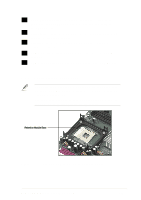
1 CPU socket. A 478-pin surface mount, Zero Insertion Force (ZIF) socket called mPGA478 B. This socket accommodates the Intel® Pentium® 4 478/Northwood Processor with 400MHz system bus. 2 North bridge controller. This controller called the Intel Memory Controller Hub (MCH) is one of the two major components of the Intel 845 (Brookdale) chipset. The MCH along with the south bridge Intel I/O Controller Hub 2 (ICH2) are interconnected through the Intel proprietary Hub interface. The MCH provides the processor interface, system memory interface, AGP interface, and Hub Interface. 3 SDRAM DIMM sockets. These three 168-pin DIMM sockets support up to 3GB using unbuffered ECC or non-ECC PC100/133 SDRAM DIMMs. 4 Super I/O chipset. This Low Pin Count (LPC) chipset combines the commonly used Super I/O functionality and system hardware monitoring capability. The chipset incorporates Fan Speed Control Monitor (FSCM), event wake-up feature, floppy disk controller, keyboard/mouse controller, a parallel port, two enhanced serial ports (one with infrared support), watchdog timer, and a MIDI interface compatible with MPU-401 UART mode. 5 ATX power connector. This 20-pin connector connects to an ATX 12V power supply. The power supply must have at least 1A on the +5V standby lead (+5VSB). 6 IDE connectors. These dual-channel bus master IDE connectors support up to four Ultra DMA/100/66, PIO Modes 3 & 4 IDE devices. Both the primary (blue) and secondary (black) connectors are slotted to prevent incorrect insertion of the IDE ribbon cable. 7 Floppy disk connector. This connector accommodates the provided ribbon cable for the floppy disk drive. One side of the connector is slotted to prevent incorrect insertion of the floppy disk cable. 8 Flash EEPROM. This 2Mb firmware contains the programmable BIOS program. 9 DIP switches. This 10-switch Dual Inline Package (DIP) allows you to set the CPU external frequency. ASUS P4B-MX motherboard user guide 1-3
-
 1
1 -
2
-
3
-
4
-
5
-
6
-
7
-
8
-
9
-
 10
10 -
 11
11 -
 12
12 -
 13
13 -
 14
14 -
 15
15 -
 16
16 -
 17
17 -
 18
18 -
 19
19 -
 20
20 -
21
-
22
-
23
-
24
-
25
-
26
-
27
-
28
-
29
-
30
-
31
-
32
-
33
-
34
-
35
-
36
-
37
-
38
-
39
-
40
-
41
-
42
-
43
-
44
-
45
-
46
-
47
-
48
-
49
-
50
-
51
-
52
-
53
-
54
-
55
-
56
-
57
-
58
-
59
-
60
-
61
-
62
-
63
-
64
-
65
-
66
-
67
-
68
-
69
-
70
-
71
-
72
-
73
-
74
-
75
-
76
-
77
-
78
-
79
-
80
-
81
-
82
-
83
-
84
-
85
-
86
-
87
-
88
-
89
-
90
-
91
-
92
-
93
-
94
-
95
-
96
-
97
-
98
-
99
-
100
-
101
-
102
-
103
-
104
-
105
-
106
-
107
-
108
-
109
-
110
-
111
-
112
 |
 |
