Asus P4T533 P4T533 User Manual - Page 24
Before you proceed - c 20 pin panel
 |
View all Asus P4T533 manuals
Add to My Manuals
Save this manual to your list of manuals |
Page 24 highlights
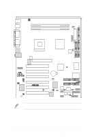
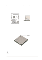
19) SMARTCON p. 41 Smart Card Reader connector (14-1 pin) (optional) 20) FP_LO_SWL, FP_LO_SWR p. 41 Line-out Selector Jumpers (Two 2 pin) 21) AFPANEL p. 42 ASUS iPanel / Infrared Connector (24-1 pin) 22) LINE_IN p. 43 Front Panel Audio Line In Header (5 pin) 23) AAPANEL p. 43 Front Panel Audio Connector (10-1 pin) 24) SPDIF p. 44 Digital Audio Connector (4-1 pin) (optional) 25) GAME p. 44 Game Header (16-1 pin GAME) 26) TRPWR p. 45 Power Supply Thermal Connector (2 pin) 27) PLED p. 46 Keyboard Lock Switch Lead (2 pin) 28) KEYLOCK p. 46 Keyboard Lock Switch Lead (2 pin) 29) SPEAKER p. 46 System Warning Speaker Lead (4 pin) 30) MLED p. 46 System Message LED Lead (2 pin) 31) SMI p. 46 System Management Interrupt Lead (2 pin) 32) PWRSW p. 46 ATX Power Switch / Soft-Off Switch Lead (2 pin) 33) RESET p. 46 Reset Switch Lead (2-pin) 2.3 Before you proceed Take note of the following precautions before you install motherboard components or change any motherboard settings. 1. Unplug the power cord from the wall socket before touching any component. 2. Use a grounded wrist strap or touch a safely grounded object or to a metal object, such as the power supply case, before handling components to avoid damaging them due to static electricity. 3. Hold components by the edges and do not to touch the ICs on them. 4. Whenever you uninstall any component, place it on a grounded antistatic pad or in the bag that came with the component. 5 Before you install or remove any component, ensure that the ATX power supply is switched off or the power cord is detached from the power supply. Failure to do so may cause severe damage to the motherboard, peripherals, and/or components. 10 Chapter 2: Hardware information
-
 1
1 -
2
-
3
-
4
-
5
-
6
-
7
-
8
-
9
-
10
-
11
-
12
-
13
-
14
-
15
-
16
-
17
-
18
-
 19
19 -
 20
20 -
 21
21 -
 22
22 -
 23
23 -
 24
24 -
 25
25 -
 26
26 -
 27
27 -
 28
28 -
 29
29 -
30
-
31
-
32
-
33
-
34
-
35
-
36
-
37
-
38
-
39
-
40
-
41
-
42
-
43
-
44
-
45
-
46
-
47
-
48
-
49
-
50
-
51
-
52
-
53
-
54
-
55
-
56
-
57
-
58
-
59
-
60
-
61
-
62
-
63
-
64
-
65
-
66
-
67
-
68
-
69
-
70
-
71
-
72
-
73
-
74
-
75
-
76
-
77
-
78
-
79
-
80
-
81
-
82
-
83
-
84
-
85
-
86
-
87
-
88
-
89
-
90
-
91
-
92
-
93
-
94
-
95
-
96
-
97
-
98
-
99
-
100
-
101
-
102
-
103
-
104
-
105
-
106
-
107
-
108
-
109
-
110
-
111
-
112
-
113
-
114
-
115
-
116
-
117
-
118
-
119
-
120
-
121
-
122
-
123
-
124
-
125
-
126
-
127
-
128
-
129
-
130
-
131
-
132
-
133
-
134
-
135
-
136
 |
 |
