Asus P4T533 P4T533 User Manual - Page 54
Hardware information, Internal audio connectors Three 4-pin CD, AUX, MODEM, Chassis Open
 |
View all Asus P4T533 manuals
Add to My Manuals
Save this manual to your list of manuals |
Page 54 highlights
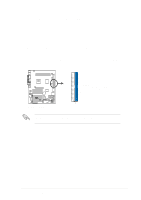
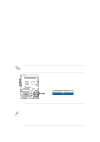
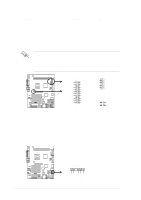
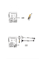
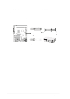
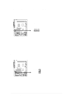
17. Internal audio connectors (Three 4-pin CD, AUX, MODEM) (optional) These connectors allow you to receive stereo audio input from sound sources such as a CD-ROM, TV tuner, or MPEG card. The MODEM connector allows the onboard audio to interface with a voice modem card with a similar connector. It also allows the sharing of mono_in (such as a phone) and a mono_out (such as a speaker) between the audio and a voice modem card. MODEM Modem-In Left Audio Channel Ground Ground Ground Ground P4T533 Modem-Out Right Audio Channel ® AUX (White) CD(Black) P4T533 Internal Audio Connectors 18. Chassis Open Alarm Lead (4-1 pin CHASSIS) This lead is intended for a chassis that supports intrusion detection. The lead requires an external detection mechanism such as a chassis intrusion monitor/sensor or microswitch. When any chassis component is removed, the sensor is triggered and a high-level signal is sent to this lead to record a chassis intrusion event. The event is then be processed by software such as LDCM. When not using the chassis intrusion lead, place a jumper cap over the pins to close the circuit. Removing the jumper cap prevents the system from booting up. CHASSIS +5VSB_MB Chassis Signal GND P4T533 ® P4T533 Chassis Alarm Lead 40 Chapter 2: Hardware information
-
 1
1 -
2
-
3
-
4
-
5
-
6
-
7
-
8
-
9
-
10
-
11
-
12
-
13
-
14
-
15
-
16
-
17
-
18
-
19
-
20
-
21
-
22
-
23
-
24
-
25
-
26
-
27
-
28
-
29
-
30
-
31
-
32
-
33
-
34
-
35
-
36
-
37
-
38
-
39
-
40
-
41
-
42
-
43
-
44
-
45
-
46
-
47
-
48
-
 49
49 -
 50
50 -
 51
51 -
 52
52 -
 53
53 -
 54
54 -
 55
55 -
 56
56 -
 57
57 -
 58
58 -
 59
59 -
60
-
61
-
62
-
63
-
64
-
65
-
66
-
67
-
68
-
69
-
70
-
71
-
72
-
73
-
74
-
75
-
76
-
77
-
78
-
79
-
80
-
81
-
82
-
83
-
84
-
85
-
86
-
87
-
88
-
89
-
90
-
91
-
92
-
93
-
94
-
95
-
96
-
97
-
98
-
99
-
100
-
101
-
102
-
103
-
104
-
105
-
106
-
107
-
108
-
109
-
110
-
111
-
112
-
113
-
114
-
115
-
116
-
117
-
118
-
119
-
120
-
121
-
122
-
123
-
124
-
125
-
126
-
127
-
128
-
129
-
130
-
131
-
132
-
133
-
134
-
135
-
136
 |
 |
