Asus P5N-D User Manual - Page 52
Serial ATA connectors 7-pin SATA1-4
 |
UPC - 610839159123
View all Asus P5N-D manuals
Add to My Manuals
Save this manual to your list of manuals |
Page 52 highlights
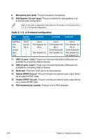
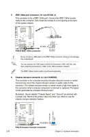
• Pin 20 on the IDE connector is removed to match the covered hole on the Ultra DMA cable connector. This prevents incorrect insertion when you connect the IDE cable. • Use the 80-conductor IDE cable for Ultra DMA 133/100/66 IDE devices. If any device jumper is set as "Cable-Select," make sure all other device jumpers have the same setting. 3. Serial ATA connectors (7-pin SATA1-4) These connectors are for the Serial ATA signal cables for Serial ATA hard disk drives. If you installed Serial ATA hard disk drives, you can create a RAID 0, RAID 1, RAID 0+1, RAID 5, or JBOD configuration�w��it�h��th�e��o�n�b��o�a�r�d�N��V�I�D��IA�® MediaShield™ RAID controller. ® P5N-D P5N-D SATA connectors SATA1 SATA2 SATA3 SATA4 GND RSATA_TXP1 RSATA_TXN1 GND RSATA_RXP1 RSATA_RXN1 GND GND RSATA_TXP2 RSATA_TXN2 GND RSATA_RXP2 RSATA_RXN2 GND GND RSATA_TXP3 RSATA_TXN3 GND RSATA_RXP3 RSATA_RXN3 GND GND RSATA_TXP4 RSATA_TXN4 GND RSATA_RXP4 RSATA_RXN4 GND The RAID function of these connectors is set to [Disabled] by default. If you intend to create a Serial ATA RAID set using these connectors, enable the RAID Enabled item under the Serial ATA Configuration sub-menu in the BIOS. These connectors support Native Command Queuing (NCQ), Power Management (PM) Implementation Algorithm, Hot Swap and smart setup. 2-28 Chapter 2: Hardware information
-
 1
1 -
2
-
3
-
4
-
5
-
6
-
7
-
8
-
9
-
10
-
11
-
12
-
13
-
14
-
15
-
16
-
17
-
18
-
19
-
20
-
21
-
22
-
23
-
24
-
25
-
26
-
27
-
28
-
29
-
30
-
31
-
32
-
33
-
34
-
35
-
36
-
37
-
38
-
39
-
40
-
41
-
42
-
43
-
44
-
45
-
46
-
 47
47 -
 48
48 -
 49
49 -
 50
50 -
 51
51 -
 52
52 -
 53
53 -
 54
54 -
 55
55 -
 56
56 -
 57
57 -
58
-
59
-
60
-
61
-
62
-
63
-
64
-
65
-
66
-
67
-
68
-
69
-
70
-
71
-
72
-
73
-
74
-
75
-
76
-
77
-
78
-
79
-
80
-
81
-
82
-
83
-
84
-
85
-
86
-
87
-
88
-
89
-
90
-
91
-
92
-
93
-
94
-
95
-
96
-
97
-
98
-
99
-
100
-
101
-
102
-
103
-
104
-
105
-
106
-
107
-
108
-
109
-
110
-
111
-
112
-
113
-
114
-
115
-
116
-
117
-
118
-
119
-
120
-
121
-
122
-
123
-
124
-
125
-
126
-
127
-
128
-
129
-
130
-
131
-
132
-
133
-
134
-
135
-
136
-
137
-
138
-
139
-
140
-
141
-
142
-
143
-
144
-
145
-
146
-
147
-
148
-
149
-
150
-
151
-
152
-
153
-
154
-
155
-
156
-
157
-
158
-
159
-
160
-
161
-
162
-
163
-
164
 |
 |
