Asus PRIME Z270-K PRIME Z270-K Users manual English - Page 14
M.2 socket 3, Intel, Z270 Serial ATA 6.0Gb/s connectors 7-pin, SATA6G_1~6 - drivers
 |
View all Asus PRIME Z270-K manuals
Add to My Manuals
Save this manual to your list of manuals |
Page 14 highlights
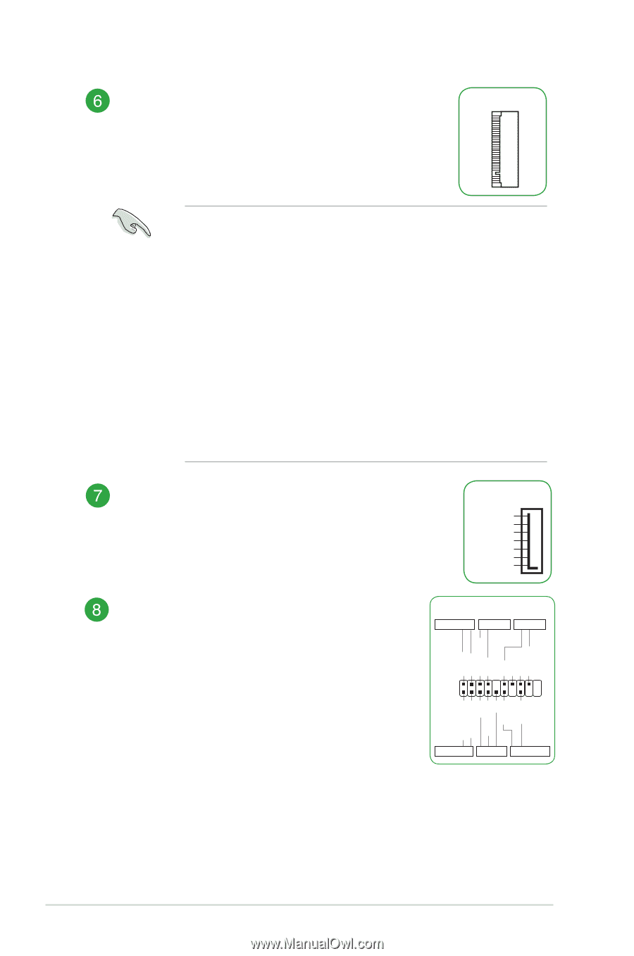
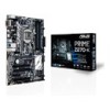
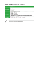
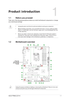
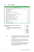
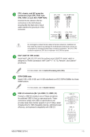
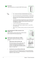
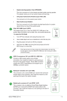
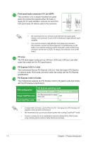
M.2 socket 3 These sockets allow you to install M.2 (NGFF) SSD modules. M.2(SOCKET3) • M.2_1 socket supports M Key and 2242/2260/2280 storage devices. • M.2_2 socket supports M Key and 2242/2260/2280/22110 storage devices. • When using Intel® Desktop Responsiveness technologies with PCIe/SATA M.2 device, ensure to set up the Windows® UEFI operating system under RAID mode. • Intel® Optane Technology only supported when using 7th Generation Intel® processors. Before using Intel® Optane memory modules, ensure that you have updated your motherboard drivers and BIOS to the latest version from ASUS support website. • The M.2 slots support data transfer speed up to 32Gb/s. • When a device in SATA mode is installed on the M.2_1 socket, SATA_1 port cannot be used. • When a device is installed on the M.2_2 socket, SATA_5/6 ports cannot be used. Intel® Z270 Serial ATA 6.0Gb/s connectors (7-pin SATA6G_1~6) These connectors connect to Serial ATA 6.0 Gb/s hard disk drives via Serial ATA 6.0 Gb/s signal cables. SATA6G GND RSATA_TXP RSATA_TXN GND RSATA_RXN RSATA_RXP GND System panel connector (20-5 pin F_PANEL) This connector supports several chassis-mounted functions. PANEL +PWR_LED- PWR_SW SPEAKER PLED+ PLEDPWRBTN# GND +5V GND GND Speaker • System power LED (4-pin PWR_LED) This 4-pin connector is for the system power LED. Connect the chassis power LED cable to this connector. The system power LED lights up when you turn on the system power, and blinks when the system is in sleep mode. HDD_LED+ HDD_LED- GND RSTCON# NC PLED+ PLED- PIN 1 +HDD_LED- RESET +PWR_LED* Requires an ATX power supply • Hard disk drive activity LED (2-pin HDD_LED) This 2-pin connector is for the HDD Activity LED. Connect the HDD Activity LED cable to this connector. The HDD LED lights up or flashes when data is read from or written to the HDD. 1-4 Chapter 1: Product introduction
-
 1
1 -
2
-
3
-
4
-
5
-
6
-
7
-
8
-
 9
9 -
 10
10 -
 11
11 -
 12
12 -
 13
13 -
 14
14 -
 15
15 -
 16
16 -
 17
17 -
 18
18 -
 19
19 -
20
-
21
-
22
-
23
-
24
-
25
-
26
-
27
-
28
-
29
-
30
-
31
-
32
-
33
-
34
-
35
-
36
-
37
-
38
-
39
-
40
-
41
-
42
-
43
-
44
-
45
-
46
-
47
-
48
-
49
-
50
-
51
-
52
-
53
-
54
-
55
-
56
-
57
-
58
-
59
-
60
-
61
-
62
-
63
-
64
-
65
-
66
-
67
-
68
-
69
-
70
-
71
-
72
-
73
-
74
-
75
-
76
 |
 |