Asus RS920A-E6 RS8 User Guide - Page 55
Layout contents
 |
View all Asus RS920A-E6 RS8 manuals
Add to My Manuals
Save this manual to your list of manuals |
Page 55 highlights
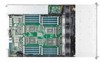
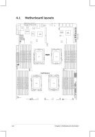
Layout contents Jumpers 1. Clear RTC RAM (CLRTC1) 2. VGA controller setting (3-pin VGA_SW1) 3. LAN controller setting (3-pin LAN_SW1) 4. DDR3 voltage control setting (4-pin LVDDR3_SEL1; LVDDR3_SEL2; LVDDR3_SEL3,LVDDR3_SEL4) 5. Force BIOS recovery setting (3-pin RECOVERY1) Page 4-4 4-5 4-6 4-6 4-7 Internal connectors 1. Serial ATA connectors (7-pin SATA1-6 [blue], SAS 1-4 [blue], SAS 5-8 [black]) 2. USB connector (10-1 pin USB34, A-Type USB5) 3. Front fan connectors (4-pin FRNT_FAN1-5) 4. Serial General Purpose Input/Output connector (6-1 pin SGPIO1-4) 5. Power Supply SMBus connector (5-pin JP1) 6. SSI power connectors (24-pin PWR1, 8-pin PWR2) 7. System panel connector (20-pin PANEL1) 8. Auxiliary panel connector (20-pin AUX_PANEL1) Page 4-9 4-9 4-10 4-12 4-12 4-13 4-14 4-15 ASUS RS920A-E6/RS8; RS924A-E6/RS8 4-3
-
 1
1 -
2
-
3
-
4
-
5
-
6
-
7
-
8
-
9
-
10
-
11
-
12
-
13
-
14
-
15
-
16
-
17
-
18
-
19
-
20
-
21
-
22
-
23
-
24
-
25
-
26
-
27
-
28
-
29
-
30
-
31
-
32
-
33
-
34
-
35
-
36
-
37
-
38
-
39
-
40
-
41
-
42
-
43
-
44
-
45
-
46
-
47
-
48
-
49
-
 50
50 -
 51
51 -
 52
52 -
 53
53 -
 54
54 -
 55
55 -
 56
56 -
 57
57 -
 58
58 -
 59
59 -
 60
60 -
61
-
62
-
63
-
64
-
65
-
66
-
67
-
68
-
69
-
70
-
71
-
72
-
73
-
74
-
75
-
76
-
77
-
78
-
79
-
80
-
81
-
82
-
83
-
84
-
85
-
86
-
87
-
88
-
89
-
90
-
91
-
92
-
93
-
94
-
95
-
96
-
97
-
98
-
99
-
100
-
101
-
102
-
103
-
104
-
105
-
106
-
107
-
108
-
109
-
110
-
111
-
112
-
113
-
114
-
115
-
116
-
117
-
118
-
119
-
120
-
121
-
122
-
123
-
124
-
125
-
126
-
127
-
128
-
129
-
130
-
131
-
132
-
133
-
134
-
135
-
136
-
137
-
138
-
139
-
140
-
141
-
142
-
143
-
144
-
145
-
146
-
147
-
148
-
149
-
150
-
151
-
152
-
153
-
154
-
155
-
156
-
157
-
158
-
159
-
160
-
161
-
162
 |
 |
