Asus SP97 User Manual - Page 20
System Memory SIMM - v socket 7
 |
View all Asus SP97 manuals
Add to My Manuals
Save this manual to your list of manuals |
Page 20 highlights
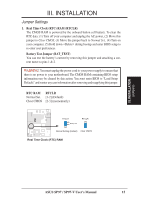
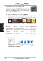
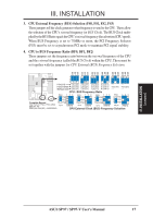
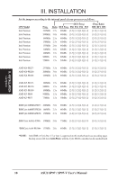
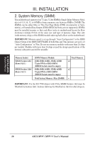
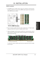
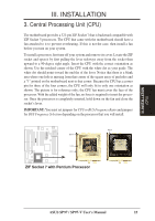
III. INSTALLATION 2. System Memory (SIMM) This motherboard supports four 72-pin, 32-bit SIMMs (Single Inline Memory Modules) of 4, 8, 16, 32, or 64MB to form a memory size between 8MB to 256MB. The SIMMs can be either 60ns or 70ns Fast Page Mode (FPM) (Asymmetric or Symmetric), or Extended Data Output (EDO) (BEDO & Parity are not supported). SIMMs must be installed in pairs so that each Row (refer to motherboard layout for Row locations) contains 64-bits of the same size and type of memory chips. One side (with memory chips) of the SIMM module takes up half a Row on the motherboard. IMPORTANT: Memory speed is set up through "Auto Configuration" in the BIOS Chipset Setup of the BIOS SOFTWARE. If both 60ns and 70ns memory are used, set "Auto Configuration" to 70ns. Do not use memory modules with more than 24 chips per module. Modules with more than 24 chips exceed the design specifications of the memory subsystem and will be unstable. Memory Socket SIMM Sockets 1&2 (Rows 0 & 1) SIMM Sockets 3&4 (Rows 2 & 3) SIMM Memory Module 4MB, 8MB, 16MB, 32MB, 64MB 72-pin FPM or EDO SIMM (DIMM Sockets must be empty) 4MB, 8MB, 16MB, 32MB, 64MB 72-pin FPM or EDO SIMM (DIMM Sockets must be empty) Total System Memory (Max 256MB) Total Memory x2 x2 = IMPORTANT: For the SiS 5598 chipset with VGA, SIMM Sockets 1&2 must be filled before Sockets 3&4. Sockets 3&4 may be filled before 1&2 for other chipsets. III. INSTALLATION (System Memory) 20 ASUS SP97 / SP97-V User's Manual
-
 1
1 -
2
-
3
-
4
-
5
-
6
-
7
-
8
-
9
-
10
-
11
-
12
-
13
-
14
-
 15
15 -
 16
16 -
 17
17 -
 18
18 -
 19
19 -
 20
20 -
 21
21 -
 22
22 -
 23
23 -
 24
24 -
 25
25 -
26
-
27
-
28
-
29
-
30
-
31
-
32
-
33
-
34
-
35
-
36
-
37
-
38
-
39
-
40
-
41
-
42
-
43
-
44
-
45
-
46
-
47
-
48
-
49
-
50
-
51
-
52
-
53
-
54
-
55
-
56
-
57
-
58
-
59
-
60
-
61
-
62
-
63
-
64
-
65
-
66
-
67
-
68
-
69
-
70
-
71
-
72
-
73
-
74
-
75
-
76
-
77
-
78
-
79
-
80
-
81
-
82
-
83
-
84
-
85
-
86
-
87
-
88
-
89
-
90
-
91
-
92
-
93
-
94
-
95
-
96
 |
 |
