Asus SP97 User Manual - Page 28
Power Supply, Chassis Fan Connectors PWR_, CPU_, CHA_FAN, 3 pins
 |
View all Asus SP97 manuals
Add to My Manuals
Save this manual to your list of manuals |
Page 28 highlights
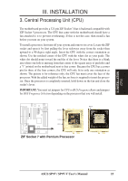
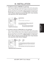
III. INSTALLATION 5. Power Supply, Chassis Fan Connectors (PWR_, CPU_, CHA_FAN, 3 pins) This connector supports a 3-pin cooling fan of 500mAmp (6watts) or less with a minimum of 3,500RPM. Depending on the fan manufacturer, the wiring and plug may be different. The red wire should be Positive and the black wire should be Ground. WARNING! Damage may occur to the motherboard and/or the fans if these pins are incorrectly used. DO NOT PLACE JUMPER CAPS OVER THESE PINS. Power Supply, CPU Fan Power Chassis Fan Power R (NC) +12 Volt Ground III. INSTALLATION (Connectors) 12Volt CPU Fan Power 6. Primary/Secondary IDE Connectors (two 40-1 pin blocks) These connectors support the provided IDE hard disk ribbon cable. After connecting the single end to the board, connect the two plugs at the other end to your hard disk(s). If you install two hard disks, you must set the second drive to Slave mode. Refer to the documentation of your hard disk for the jumper settings. BIOS now supports SCSI device or IDE CD-ROM bootup (see HDD Sequence SCSI/IDE First & Boot Sequence in the BIOS Features Setup of the BIOS SOFTWARE) (Pin 20 is removed to prevent inserting in the wrong orientation when using ribbon cables with pin 20 plugged). Pin 1 Orient the red stripe on the IDE ribbon cable to pin 1 R Secondary IDE Connector Primary IDE Connector IDE (Hard Disk Drive) Connectors TIP: You can configure two hard disks to be both Masters using one ribbon cable on the primary IDE connector and another ribbon cable on the secondary IDE connector. You may install one operating system on an IDE drive and another on a SCSI drive, and then select the boot disk through the BIOS Features Setup. 28 ASUS SP97 / SP97-V User's Manual
-
 1
1 -
2
-
3
-
4
-
5
-
6
-
7
-
8
-
9
-
10
-
11
-
12
-
13
-
14
-
15
-
16
-
17
-
18
-
19
-
20
-
21
-
22
-
 23
23 -
 24
24 -
 25
25 -
 26
26 -
 27
27 -
 28
28 -
 29
29 -
 30
30 -
 31
31 -
 32
32 -
 33
33 -
34
-
35
-
36
-
37
-
38
-
39
-
40
-
41
-
42
-
43
-
44
-
45
-
46
-
47
-
48
-
49
-
50
-
51
-
52
-
53
-
54
-
55
-
56
-
57
-
58
-
59
-
60
-
61
-
62
-
63
-
64
-
65
-
66
-
67
-
68
-
69
-
70
-
71
-
72
-
73
-
74
-
75
-
76
-
77
-
78
-
79
-
80
-
81
-
82
-
83
-
84
-
85
-
86
-
87
-
88
-
89
-
90
-
91
-
92
-
93
-
94
-
95
-
96
 |
 |
