Asus TS300-E5 User Guide - Page 45
Cable connections - pa4 bios
 |
UPC - 610839652525
View all Asus TS300-E5 manuals
Add to My Manuals
Save this manual to your list of manuals |
Page 45 highlights
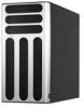
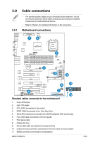
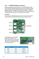
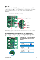
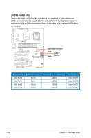
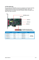
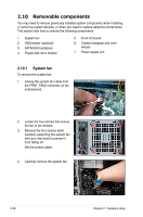
2.9 Cable connections • The bundled system cables are pre-connected before shipment. You do not need to disconnect these cables unless you will remove pre‑installed components to install additional devices. • Refer to Chapter 4 for detailed information on the connectors. 2.9.1 PS/2KBMS T: Mouse B: Keyboard LAN_USB12 Motherboard24.c5comn(9n.6ien)ctions ATXPWR1 ATX12V1 1 ISL 2 6312 COM1 BCM 5721 Intel Bigby-p MCH LGA775 VGA1 BCM 5721 LAN1_LAN2 LAN3_LAN4 ® P5BP-E/4L DDR2 DIMM_A1 (64 bit,240-pin module) DDR2 DIMM_A2 (64 bit,240-pin module) DDR2 DIMM_B1 (64 bit,240-pin module) DDR2 DIMM_B2 (64 bit,240-pin module) 3 CPU_FAN1 CPUFAN_SET1 CHAFAN_SET1 FRNT_FAN1 30.5cm (12in) CR2032 3V Lithium Cell CMOS Power FRNT_FAN2 4 FRNT_FAN3 RAID_SEL1 SATA1 PCIE1 BCM 5721 PCIE2 BUZZ1 5 Intel ICH7R SATA2 SATA3 SATA4 CLRTC1 9 PRI_IDE1 BCM 5721 PCI3 RECOVERY1 ASMB3 CMI9880 XGI Z9s REAR_FAN1 HDLED1 PCIE4 COM2 PCI5 8Mb BIOS 8PCI6 FLOPPY1 Super I/O SB_PWR1 6 USB34 7 1 AUX_PANEL1 PANEL1 11 10 Standard cables connected to the motherboard 1. 24-pin ATX power 2. 4-pin 12V power 3. CPU_FAN1 (connected to the cooler) 4. FRNT_FAN2 (connected to the 12cm Rear Fan) 5. Serial ATA connectors [connected to the SATA backplane (PA4 model only)] 6. Front USB cable (connected to the front panel) 7. Front panel cable 8. Floppy disk drive 9. Primary IDE cable (connected to the optional drive) 10. Chassis Intrusion connector (connected to the rear chassis intrusion switch) 11. SMBus connector (connected to the backplane) ASUS TS300-E5 2-23
-
 1
1 -
2
-
3
-
4
-
5
-
6
-
7
-
8
-
9
-
10
-
11
-
12
-
13
-
14
-
15
-
16
-
17
-
18
-
19
-
20
-
21
-
22
-
23
-
24
-
25
-
26
-
27
-
28
-
29
-
30
-
31
-
32
-
33
-
34
-
35
-
36
-
37
-
38
-
39
-
 40
40 -
 41
41 -
 42
42 -
 43
43 -
 44
44 -
 45
45 -
 46
46 -
 47
47 -
 48
48 -
 49
49 -
 50
50 -
51
-
52
-
53
-
54
-
55
-
56
-
57
-
58
-
59
-
60
-
61
-
62
-
63
-
64
-
65
-
66
-
67
-
68
-
69
-
70
-
71
-
72
-
73
-
74
-
75
-
76
-
77
-
78
-
79
-
80
-
81
-
82
-
83
-
84
-
85
-
86
-
87
-
88
-
89
-
90
-
91
-
92
-
93
-
94
-
95
-
96
-
97
-
98
-
99
-
100
-
101
-
102
-
103
-
104
-
105
-
106
-
107
-
108
-
109
-
110
-
111
-
112
-
113
-
114
-
115
-
116
-
117
-
118
-
119
-
120
-
121
-
122
-
123
-
124
-
125
-
126
-
127
-
128
-
129
-
130
-
131
-
132
-
133
-
134
-
135
-
136
-
137
-
138
-
139
-
140
-
141
-
142
-
143
-
144
-
145
-
146
-
147
-
148
-
149
-
150
-
151
-
152
-
153
-
154
-
155
-
156
-
157
-
158
-
159
-
160
-
161
-
162
-
163
-
164
-
165
-
166
-
167
-
168
-
169
-
170
-
171
-
172
-
173
-
174
-
175
-
176
-
177
-
178
-
179
-
180
-
181
-
182
-
183
-
184
-
185
-
186
-
187
-
188
-
189
-
190
-
191
-
192
-
193
-
194
-
195
-
196
-
197
-
198
-
199
-
200
-
201
-
202
-
203
-
204
-
205
-
206
-
207
-
208
 |
 |