Asus TS300-E5 User Guide - Page 47
SATA/SAS backplane jumper settings and HDD ID assignments
 |
UPC - 610839652525
View all Asus TS300-E5 manuals
Add to My Manuals
Save this manual to your list of manuals |
Page 47 highlights
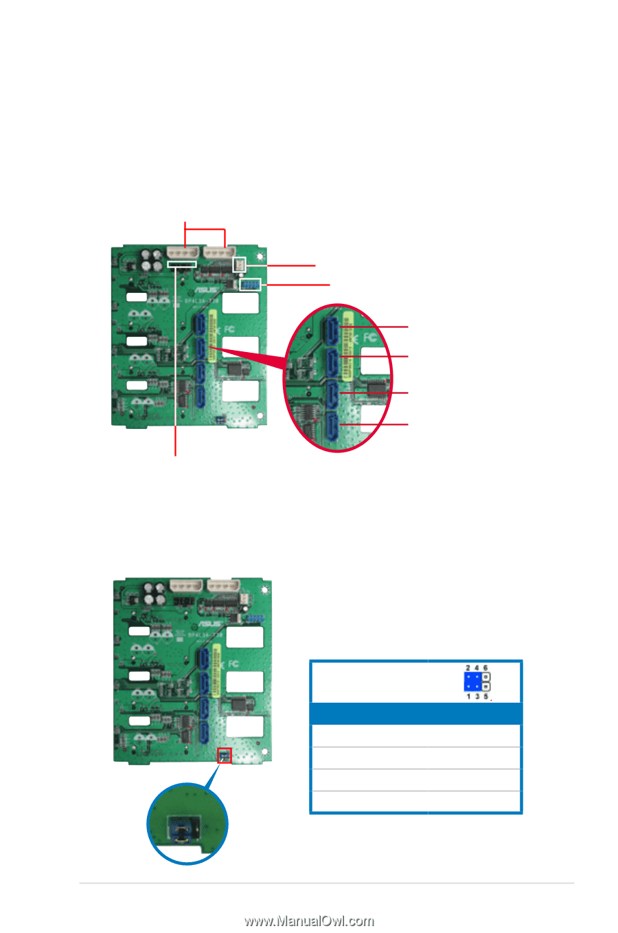
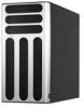
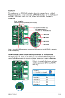
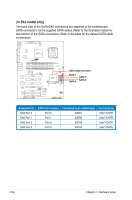
Back side The back side of the SATA/SAS backplane faces the rear panel when installed. This side includes the power connectors, SATA/SAS interfaces for the motherboard Serial ATA connectors or the SAS card, an HDD fan connector, and SMBus connectors. Power connectors (connect power plugs from the power supply) Fan connector (for HDD fan) SAS HDD Activity LED connector (for PX4 model only) SAS Port 0 SAS Port 1 SAS Port 2 SAS Port 3 Upper 6-1 pins (J1): SMBus connector (connects the SMB cable from the AUX_PANEL1 connector on the motherboard) SATA/SAS backplane jumper settings and HDD ID assignments The 6-pin jumper J3 allows you to define your desired SATA/SAS configuration. The picture below shows the location of jumper J3 with pins 1-3 and 2-4 shorted. Refer to the table for the jumper settings and the appropriate ID# for each SATA HDD bay. J3 setting (1-3 shorted, 2-4 shorted) Device Drive Bay 1 Drive Bay 2 Drive Bay 3 Drive Bay 4 SATA/SAS ID ID0 ID1 ID2 ID3 ASUS TS300-E5 2-25
-
 1
1 -
2
-
3
-
4
-
5
-
6
-
7
-
8
-
9
-
10
-
11
-
12
-
13
-
14
-
15
-
16
-
17
-
18
-
19
-
20
-
21
-
22
-
23
-
24
-
25
-
26
-
27
-
28
-
29
-
30
-
31
-
32
-
33
-
34
-
35
-
36
-
37
-
38
-
39
-
40
-
41
-
 42
42 -
 43
43 -
 44
44 -
 45
45 -
 46
46 -
 47
47 -
 48
48 -
 49
49 -
 50
50 -
 51
51 -
 52
52 -
53
-
54
-
55
-
56
-
57
-
58
-
59
-
60
-
61
-
62
-
63
-
64
-
65
-
66
-
67
-
68
-
69
-
70
-
71
-
72
-
73
-
74
-
75
-
76
-
77
-
78
-
79
-
80
-
81
-
82
-
83
-
84
-
85
-
86
-
87
-
88
-
89
-
90
-
91
-
92
-
93
-
94
-
95
-
96
-
97
-
98
-
99
-
100
-
101
-
102
-
103
-
104
-
105
-
106
-
107
-
108
-
109
-
110
-
111
-
112
-
113
-
114
-
115
-
116
-
117
-
118
-
119
-
120
-
121
-
122
-
123
-
124
-
125
-
126
-
127
-
128
-
129
-
130
-
131
-
132
-
133
-
134
-
135
-
136
-
137
-
138
-
139
-
140
-
141
-
142
-
143
-
144
-
145
-
146
-
147
-
148
-
149
-
150
-
151
-
152
-
153
-
154
-
155
-
156
-
157
-
158
-
159
-
160
-
161
-
162
-
163
-
164
-
165
-
166
-
167
-
168
-
169
-
170
-
171
-
172
-
173
-
174
-
175
-
176
-
177
-
178
-
179
-
180
-
181
-
182
-
183
-
184
-
185
-
186
-
187
-
188
-
189
-
190
-
191
-
192
-
193
-
194
-
195
-
196
-
197
-
198
-
199
-
200
-
201
-
202
-
203
-
204
-
205
-
206
-
207
-
208
 |
 |