Asus TS500-E5 PA4 User Guide - Page 50
Fasten the two screws on
 |
View all Asus TS500-E5 PA4 manuals
Add to My Manuals
Save this manual to your list of manuals |
Page 50 highlights
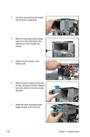
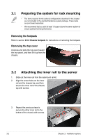
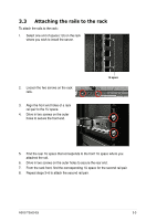
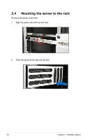
3. Insert the redundant power supply into the power supply bay. 4. Make the redundant power supply cage sit on the shelf ledge when fastening it to the chassis with screws. 5. Fasten the two screws on the chassis wall. 6. Slide the power supply module into the bay, and press until the release/ lock lever clicks to lock the module securely. 7. Install the other redundant power supply module as the first one. 2-30 Chapter 2: Hardware setup
-
 1
1 -
2
-
3
-
4
-
5
-
6
-
7
-
8
-
9
-
10
-
11
-
12
-
13
-
14
-
15
-
16
-
17
-
18
-
19
-
20
-
21
-
22
-
23
-
24
-
25
-
26
-
27
-
28
-
29
-
30
-
31
-
32
-
33
-
34
-
35
-
36
-
37
-
38
-
39
-
40
-
41
-
42
-
43
-
44
-
 45
45 -
 46
46 -
 47
47 -
 48
48 -
 49
49 -
 50
50 -
 51
51 -
 52
52 -
 53
53 -
 54
54 -
 55
55 -
56
-
57
-
58
-
59
-
60
-
61
-
62
-
63
-
64
-
65
-
66
-
67
-
68
-
69
-
70
-
71
-
72
-
73
-
74
-
75
-
76
-
77
-
78
-
79
-
80
-
81
-
82
-
83
-
84
-
85
-
86
-
87
-
88
-
89
-
90
-
91
-
92
-
93
-
94
-
95
-
96
-
97
-
98
-
99
-
100
-
101
-
102
-
103
-
104
-
105
-
106
-
107
-
108
-
109
-
110
-
111
-
112
-
113
-
114
-
115
-
116
-
117
-
118
-
119
-
120
-
121
-
122
-
123
-
124
-
125
-
126
-
127
-
128
-
129
-
130
-
131
-
132
-
133
-
134
-
135
-
136
-
137
-
138
-
139
-
140
-
141
-
142
-
143
-
144
-
145
-
146
-
147
-
148
-
149
-
150
-
151
-
152
-
153
-
154
-
155
-
156
-
157
-
158
-
159
-
160
-
161
-
162
-
163
-
164
 |
 |

Chapter 2:
Hardware setup
2-30
3.
Insert the redundant power supply
into the power supply bay.
4.
Make the redundant power supply
cage sit on the shelf ledge when
fastening it to the chassis with
screws.
5.
Fasten the two screws on the
chassis wall.
6.
Slide the power supply module into
the bay, and press until the release/
lock lever clicks to lock the module
securely.
7.
Install the other redundant power
supply module as the first one.