Asus Terminator P-III E787 MANUAL TERMINATOR English - Page 17
ASUS Terminator Barebone System - cpu
 |
View all Asus Terminator P-III manuals
Add to My Manuals
Save this manual to your list of manuals |
Page 17 highlights
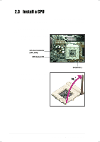
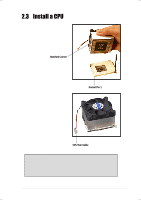
2.3 Install a CPU 3. Position the CPU above the socket such that its notched or marked corner matches the Socket Pin 1, while making sure that the CPU is parallel to the socket. Notched Corner 4. Carefully insert the CPU into the socket until it fits in place. Socket Pin 1 5. Push down the lever to secure the CPU. The lever clicks in place indicating that the socket is locked. 6. Connect the CPU fan cable to the 3-pin CPU_FAN connector on the motherboard. Refer to the picture in step 1. CPU Fan Cable WARNING! The CPU fits only in one orientation. DO NOT force the CPU into the socket to prevent bending the pins and damaging the CPU. If the CPU does not fit completely, check its orientation or check for bent pins. ASUS Terminator Barebone System 17
-
 1
1 -
2
-
3
-
4
-
5
-
6
-
7
-
8
-
9
-
10
-
11
-
 12
12 -
 13
13 -
 14
14 -
 15
15 -
 16
16 -
 17
17 -
 18
18 -
 19
19 -
 20
20 -
 21
21 -
 22
22 -
23
-
24
-
25
-
26
-
27
-
28
-
29
-
30
-
31
-
32
-
33
-
34
 |
 |
