Asus Terminator P-III E787 MANUAL TERMINATOR English - Page 18
Install System Memory
 |
View all Asus Terminator P-III manuals
Add to My Manuals
Save this manual to your list of manuals |
Page 18 highlights
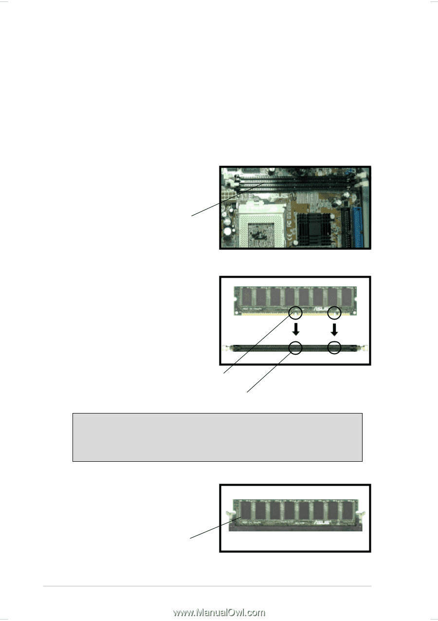
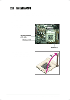
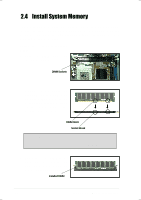
2.4 Install System Memory The motherboard includes two 168-pin Dual Inline Memory Module (DIMM) sockets. The sockets support up to 1GB system memory using PC133-compliant Synchronous Dynamic Random Access Memory (SDRAM) DIMMs. Follow these steps to install a DIMM. 1. Locate the DIMM sockets on the motherboard. DIMM Sockets 2. Unlock a DIMM socket by pressing the retaining clips outward. Align a DIMM on the socket such that the notches on the DIMM match the breaks on the socket. DIMM Notch Socket Break CAUTION! DIMMs are keyed with notches so that they fit in only one direction. DO NOT force a DIMM into a socket to avoid damaging the DIMM. 3. Firmly insert the DIMM in the socket until the retaining clips snap back in place and the DIMM is properly seated. Installed DIMM 18 Chapter 2: Basic Installation
-
 1
1 -
2
-
3
-
4
-
5
-
6
-
7
-
8
-
9
-
10
-
11
-
12
-
 13
13 -
 14
14 -
 15
15 -
 16
16 -
 17
17 -
 18
18 -
 19
19 -
 20
20 -
 21
21 -
 22
22 -
 23
23 -
24
-
25
-
26
-
27
-
28
-
29
-
30
-
31
-
32
-
33
-
34
 |
 |