Behringer NEUTRON Manual - Page 21
Patch Bay
 |
View all Behringer NEUTRON manuals
Add to My Manuals
Save this manual to your list of manuals |
Page 21 highlights
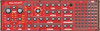
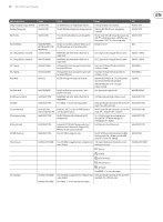
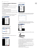
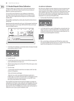
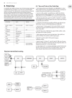
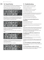
21 NEUTRON User Manual 8. Patch Bay In a patchable semi-modular synthesizer such as the Neutron, inputs and outputs are independent from one another. It is up to the user to patch the modules together as they wish. This is different from a normalized synthesizer where the functions are hard-wired together and the user just changes parameters. Patchable modular synthesizers are more complex to operate but give infinite options. Below is a table of default or normalized routings. Please refer to the numbering diagram earlier in this document. There follows a block diagram of the normalized signal flow to show how audio travels through the Neutron. DEFAULT ROUTINGS OUTPUT FROM GOES TO THEN INTO OSC MIX + EXT INPUT + NOISE ENV 1 LFO (BIPOLAR) ATTENUATOR 2 NOISE LFO (BIPOLAR) ENV 2 ASSIGN LFO (BIPOLAR) ENV 2 E. GATE1 VCF>OD>VCA>DELAY VCA CV ATT 2 PULSE WIDTH 1&2 SAMPLE AND HOLD FILTER DEPTH ENV DEPTH ATT1 CV MULT INPUT INVERT E. GATE2 LINE OUT + Headphones ATT 1 VCF FREQUENCY CV VCF FREQUENCY CV UNLESS OVERRIDDEN USING E. GATE 2 INPUT 8.1 Tips and Tricks of the Patch Bay 1. Patch Sample and Hold out into FREQ MOD in. Turn MOD DEPTH to 12 o'clock. Then Turn the S&H rate to 3 o'clock and the GLIDE to 12 0'clock. This will give you a random filter position which glides between filter cutoff points. 2. Patch LFO to PW1 and MULT 1 into INVERT IN, then INVERT OUT to PW2 for opposite direction pulse width modulation. This is a is a variation that sounds slightly different to turning ATTENUATOR 2 (see normalized routings for details). 3. With OSC 1&2 in blend mode, patch LFO to SHAPE 1. Patch MULT 1 into INVERT IN then INVERT OUT into Shape 2 for opposite direction oscillator shape shifting, a very powerful sound creation tool. 4. Set both OSC to Tone Mod Shape and ENV 2 to PW1&2 via the Mult with slow ADSR settings. This gives a rich Pulse Width Modulation (PWM) effect. 5. Patch LFO into ATT 1 IN, then patch ATT1 OUT to DELAY TIME IN. Set a short delay with the delay mix around 50% and adjust the LFO speed and shape to create a chorus effect. 6. Patch VCF 1&2 into Sum 1 A&B. Patch the output of SUM 1 into OD In. Set the filter shape to LPF to create a notch filter. 7. Patch a square wave shape LFO out to the delay time in. Then try ENV2 out patched to LFO Rate. This sounds like and 80's computer game. 8. Patch OSC 1 into OSC 2 with OSC SYNC active for frequency modulation synthesis. 9. Patch LFO into ATT 1 IN, Then ATT 1 into OSC2 with OSC SYNC active. This gives another style of FM synthesis to experiment with while using both oscillators. Try changing the position of ATT 1 to hear subtle changes. 10. Patch ASSIGN to ATT1 CV, set ASSIGN to MOD WHEEL, patch ATT1 OUT into OSC 1&2 pitch CV, this way the mod wheel sets the depth of vibrato, with LFO rate/ shape setting the characteristics and ATT2 setting the maximum depth. Neutron normalised routing. OSC 1 OSC MIX OSC 2 VCF OVERDRIVE VCA NOISE DELAY OUTPUT EXTRNAL INPUT MOD DEPTH ENV DEPTH ENV 1 VCA BIAS LFO ENV 2 ATTENUATOR FLOW UNI-POLAR LFO ATT2 PW1 OSC 1 OSC 2 PW2 ATT1 NOISE EG2 SAMPLE & HOLD INVERT BI-POLAR LFO MULT IN MULT 1 MULT 2
-
 1
1 -
2
-
3
-
4
-
5
-
6
-
7
-
8
-
9
-
10
-
11
-
12
-
13
-
14
-
15
-
 16
16 -
 17
17 -
 18
18 -
 19
19 -
 20
20 -
 21
21 -
 22
22 -
 23
23 -
 24
24 -
 25
25 -
 26
26 -
27
-
28
-
29
-
30
-
31
-
32
-
33
-
34
 |
 |