Behringer NEUTRON Manual - Page 28
Decimal to Hex Table
 |
View all Behringer NEUTRON manuals
Add to My Manuals
Save this manual to your list of manuals |
Page 28 highlights
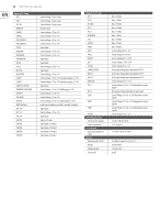
28 NEUTRON User Manual Global Setting Command Set OSC 1 autoglide Set OSC 2 autoglide Set OSC 1 range Set OSC 2 range Set OSC key split (*) Set LFO shape blend Set LFO One shot mode Set LFO rate key track key (*) Set LFO depth Set LFO ignore MIDI CLK sync Set LFO key sync Set LFO Shape order (2) Restore LFO Shape order Set LFO Shape phase Set LFO retrigger Calibration Command ASSIGN out calibration 1V ASSIGN out calibration 4V ASSIGN out calibration +V ASSIGN out calibration -V ASSIGN out save & exit Sysex F0 00 20 32 28 ID 0A 24 MM F7 F0 00 20 32 28 ID 0A 25 MM F7 F0 00 20 32 28 ID 0A 26 MM F7 F0 00 20 32 28 ID 0A 27 MM F7 F0 00 20 32 28 ID 0A 28 MM F7 F0 00 20 32 28 ID 0A 30 MM F7 F0 00 20 32 28 ID 0A 31 MM F7 F0 00 20 32 28 ID 0A 32 MM F7 F0 00 20 32 28 ID 0A 34 MM F7 F0 00 20 32 28 ID 0A 35 MM F7 F0 00 20 32 28 ID 0A 37 MM F7 F0 00 20 32 28 ID 0A 38 MM F7 F0 00 20 32 28 ID 0A 39 MM F7 F0 00 20 32 28 ID 0A 3A MM NN F7 F0 00 20 32 28 ID 0A 3B MM F7 Sysex F0 00 20 32 28 ID 10 20 F7 F0 00 20 32 28 ID 10 21 F7 F0 00 20 32 28 ID 10 23 F7 F0 00 20 32 28 ID 10 22 F7 F0 00 20 32 28 ID 10 24 F7 Notes MM = 0-24 Range is -12->+12 so 12 is no autoglide. Default:12-No autoglide Default:12-No autoglide MM = 0[32'], 1[16'], 2[8'] & 3[+/- 10 oct mode] MM = 0[32'], 1[16'], 2[8'] & 3[+/- 10 oct mode] MM = 0, 24-88. Key split note#, 0-off. Default:0-off. NB key split note# is the start of OSC2 range MM = 1-No blend, 0-Blend. Default:0-Blend MM = 1-Enabled, 0-Disabled. Default:0-Disabled MM = LFO rate root MIDI note number 12-108. 0 - Disabled MM = 0-20%, 1-40%, 2-60%, 3-80%, 4-100%. Default:4-100% MM = 0-CLK sync, 1-ignore CLK sync. Default:0-CLK sync MM = 0-Enabled, 1-Disabled. Default:0-Enabled MM = LFO Slot index: =0..4 NN = LFO shape value: = 0..4 MM - Not used MM = LFO Shape index: =0..4 NN = LFO phase value: = 0..7 - in eighths of 2*PI (or 45 degrees) MM = 0-overlapping notes will not retrigger the LFO, 1-overlapping notes will retrigger the LFO. Notes Enter calibration mode 1V Enter calibration mode 4V Increase voltage. is an optional value (2-7F) which will increase the step voltage change linearly. If omitted a value of 1 is used Decrease voltage. is an optional value (2-7F) which will increase the step voltage change linearly. If omitted a value of 1 is used Stores calibration data & exits Decimal to Hex Table The SysEx Message Payload works in Hex format. Use the Decimal to Hex Table to find the Hex value you require. All SysEx messages in the above table that have a (*) will require you to turn the Midi note number into a hex number using the table below. Dec Hex 0 0 1 1 2 2 3 3 4 4 5 5 6 6 7 7 8 8 9 9 10 A 11 B 12 C 13 D 14 E 15 F Dec Hex 32 20 33 21 34 22 35 23 36 24 37 25 38 26 39 27 40 28 41 29 42 2A 43 2B 44 2C 45 2D 46 2E 47 2F Dec Hex 64 40 65 41 66 42 67 43 68 44 69 45 70 46 71 47 72 48 73 49 74 4A 75 4B 76 4C 77 4D 78 4E 79 4F Dec Hex 96 60 97 61 98 62 99 63 100 64 101 65 102 66 103 67 104 68 105 69 106 6A 107 6B 108 6C 109 6D 110 6E 111 6F Dec Hex 16 10 17 11 18 12 19 13 20 14 21 15 22 16 23 17 24 18 25 19 26 1A 27 1B 28 1C 29 1D 30 1E 31 1F Dec Hex 48 30 49 31 50 32 51 33 52 34 53 35 54 36 55 37 56 38 57 39 58 3A 59 3B 60 3C 61 3D 62 3E 63 3F Dec Hex 80 50 81 51 82 52 83 53 84 54 85 55 86 56 87 57 88 58 89 59 90 5A 91 5B 92 5C 93 5D 94 5E 95 5F Dec Hex 112 70 113 71 114 72 115 73 116 74 117 75 118 76 119 77 120 78 121 79 122 7A 123 7B 124 7C 125 7D 126 7E 127 7F
-
 1
1 -
2
-
3
-
4
-
5
-
6
-
7
-
8
-
9
-
10
-
11
-
12
-
13
-
14
-
15
-
16
-
17
-
18
-
19
-
20
-
21
-
22
-
 23
23 -
 24
24 -
 25
25 -
 26
26 -
 27
27 -
 28
28 -
 29
29 -
 30
30 -
 31
31 -
 32
32 -
 33
33 -
34
 |
 |
