Behringer NEUTRON Manual - Page 26
Inputs TS 3.5 mm, Outputs TS 3.5 mm, Power Requirements, Enviormental, Physical
 |
View all Behringer NEUTRON manuals
Add to My Manuals
Save this manual to your list of manuals |
Page 26 highlights
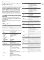
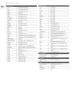
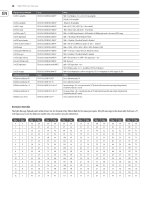
26 NEUTRON User Manual Inputs (TS 3.5 mm) OSC 1 OSC 2 OSC 1&2 INVERT IN SHAPE 1 SHAPE 2 PULSE WIDTH 1 PULSE WIDTH 2 VCF IN FREQ MOD RESONANCE OVERDRIVE IN VCA IN VCA CV DELAY IN DELAY TIME E GATE 1 E GATE 2 SAMPLE & HOLD IN SAMPLE & HOLD CLOCK LFO RATE LFO SHAPE LFO TRIG MULT (Multiple) ATT 1 IN ATT 1 CV ATT 2 IN SLEW IN SUM1(A) SUM1(B) SUM2(A) SUM2(B) Control voltage: 1 V per octave Control voltage: 1 V per octave Control voltage: 1 V per octave inverts voltage Control voltage: -5 V to +5 V Control voltage: -5 V to +5 V Control voltage: -5 V to +5 V Control voltage: -5 V to +5 V Signal input Control voltage: -5 V to +5 V Control voltage: -5 V to +5 V Signal input Signal input Control voltage: -9 V to +9 V Signal input Control voltage: -5 V to +5 V Control voltage: -5 V to +5 V (envelope triggers @ 1.5 V) Control voltage: -5 V to +5 V (envelope triggers @ 1.5 V) Signal input Control voltage: -5 V to +5 V (S&H triggers @ 3 V) Control voltage: -5 V to +5 V Control voltage: -5 V to +5 V Control voltage: -5 V to +5 V (S&H triggers @ 1.6 V) Input Signal is duplicated on Mult 1 and Mult 2 outputs Signal input Control voltage: -5 V to +5 V Signal input Signal or CV input Signal input or CV input Signal input or CV input Signal input or CV input Signal input or CV input Outputs (TS 3.5 mm) OSC 1 OSC 2 OSC Mix VCF 1 VCF 2 OVERDRIVE VCA OUTPUT NOISE ENV 1 ENV 2 INVERT LFO LFO UNI SAMPLE & HOLD MULT 1 MULT 2 MIDI GATE ATT 1 ATT 2 SLEW SUM 1 SUM 2 ASSIGN Power Requirements External power adaptor Power consumption Enviormental Operating temperature range Physical Dimensions (H x W x D) Weight Shipping weight Eurorack HP Max. +14 dBu Max. +14 dBu Max. +14 dBu Max. +12 dBu Max. +12 dBu Max. +18 dBu Max. +18 dBu Max. +15 dBu Max. +18 dBu Control voltage: 0 V to +9 V Control voltage: 0 V to +9 V inverts signals up to +/-9.5 V Control voltage: -5 V to +5 V Control voltage: 0 V to +5 V Tracks input voltage upto a maxiumum of 9.5 V Tracks input voltage upto a maxiumum of 9.5 V Tracks input voltage upto a maxiumum of 9.5 V Control voltage: 0 V to +3.3 V Control voltage -9.5 V to +9.5 V (dependant on input signal) Max output voltage dependant on input signal Control Voltage -9.5 V to +9.5 V (dependant on input signal) Control Voltage -9.5 V to +9.5 V (dependant on input signals) Control Voltage -9.5 V to +9.5 V (dependant on input signals) Control voltage: 0 V to +5 V 12 V DC, 1000 mA (12 W) 7.5-9 W typical 5 °C to 40 °C (41 °F to 104 °F) 94 x 424 x 136 mm (3.7 x 16.7 x 5.4") 2.0 kg (4.4 lbs) 3.0 kg (6.6 lbs) 80 HP
-
 1
1 -
2
-
3
-
4
-
5
-
6
-
7
-
8
-
9
-
10
-
11
-
12
-
13
-
14
-
15
-
16
-
17
-
18
-
19
-
20
-
 21
21 -
 22
22 -
 23
23 -
 24
24 -
 25
25 -
 26
26 -
 27
27 -
 28
28 -
 29
29 -
 30
30 -
 31
31 -
32
-
33
-
34
 |
 |
