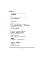
Biostar M7NCD ULTRA M7NCD Ultra user's manual - Page 14
System Operation Mode: JCLK3, Back Panel Connectors
 |
View all Biostar M7NCD ULTRA manuals
Add to My Manuals
Save this manual to your list of manuals |
Page 14 highlights
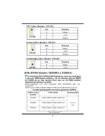
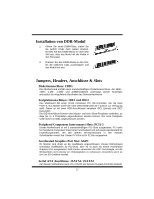
System Operation Mode: JCLK3 JCLK3 Assignment 1 Pin 1-2 Close User Mode (default) (133/ 166/ 200 MHz) Safe mode 1 Pin 1-2 Open (100 MHz) Note: When overclock function failed and system is unable to boot-up, please follow the instruction below: 1. Turn off the system. 2. Closed the JCLK3 jumper. 3. Turn on the system. 4. Enter CMOS setup menu and load defaults settings. 5. Turn off the system. 6. Open the JCLK3 jumper. 7. Turn on the system. Back Panel Connectors 12
-
 1
1 -
2
-
3
-
4
-
5
-
6
-
7
-
8
-
 9
9 -
 10
10 -
 11
11 -
 12
12 -
 13
13 -
 14
14 -
 15
15 -
 16
16 -
 17
17 -
 18
18 -
 19
19 -
20
-
21
-
22
-
23
-
24
-
25
-
26
-
27
-
28
-
29
-
30
-
31
-
32
-
33
-
34
-
35
-
36
-
37
-
38
-
39
-
40
-
41
 |
 |
12
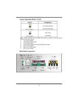
System Operation Mode: JCLK3
Note:
When overclock function failed and system is unable to boot-up, please
follow the instruction below:
1.
Turn off the system.
2.
Closed the JCLK3 jumper.
3.
Turn on the system.
4.
Enter CMOS setup menu and load defaults settings.
5.
Turn off the system.
6.
Open the JCLK3 jumper.
7.
Turn on the system.
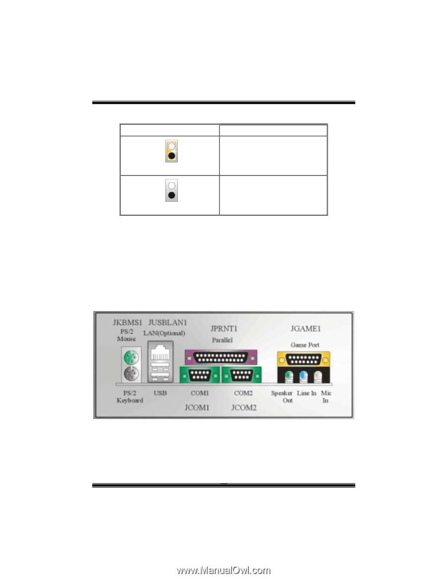
Back Panel Connectors
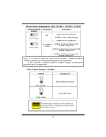
JCLK3
Assignment
1
Pin 1-2 Close
User Mode (default)
(133/ 166/ 200 MHz)
1
Pin 1-2 Open
Safe mode
(100 MHz)